|
|
Test For Presence
of Internal
Oscillator Calibration Word
for PIC 12F629 & 12F675
|
 |
Description
The PIC 12F629 and
12F675 devices have an internal 4Mhz oscillator that enables the
devices to be used without an external crystal or RC network.
This frees up one or two pins for I/O use and allows the device to
be built into minimum component count designs.
Problems arise if by accident or
otherwise, the factory programmed oscillator calibration word, located at program memory address 0x3FF is erased or over
written. If application code tries to read the calibration
word and it has been erased, the code will normally crash.
It turns out that erased calibration
words on the 12F629/675 PIC are the cause of almost all queries
relating to code on my website that uses a 12F629/675. People using JDM type
programmers and associated software seem to have this problem more
than most. This is, in part I suspect, due to the free software
/ cheap hardware used by the JDM programmer that attracts
inexperienced users.
My advise to people with problems is
to put the PIC into their programmer hardware and read out the program memory
to see if the
calibration word is present. However, experience again shows
that many users just become even more confused so I've written this
application to give a quick Good/Bad test of the calibration word.
There's also an optional bit of hardware that will display the value
of the calibration word if it's present.
How it works
If the calibration word has been erased, when the
application code tries to read it, instead of returning with the
calibration value, it wraps back round to the start of program memory as if
it had been reset. When the PIC starts
after a Power-on-reset (POR) certain internal registers are
initialised to known values. If the code wraps back round to
the reset vecotr because of a missing calibration word, unlike the Power-on-reset, these
registers are not initialised.
The application use
the fact that this wrap-around doesn't affect the
internal registers so if we alter the value in a specific register
after a power-on-reset we can
tell if it has had a Power-on-reset or the code has wrapped back round due to a missing
calibration value.
The code indicates the
result of the test as Good/Bad by blinking an LED; green LED meaning the
calibration word is present, and red LED if it has been erased.
With some extra
hardware around a 74HC595 it can also display the value of the
calibration word, if present, as a binary number using eight LEDs.
This is optional and the good/bad test works without it being
present.
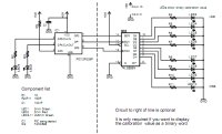
Hardware & Schematic
For the basic calibration good /
bad test, you only need to build the circuit on the left of the
dotted line in the schematic. I deliberately kept it simple so you
can quickly and easily build the test circuit.
The circuit around 74HC595 is only
used to display the binary value of the calibration word. I added it
for a bit of fun, you don't need it if you just want to test for the
presence of the calibration word.
Software
Download HEX code  (for use
with either 12F629 or 12F675) (for use
with either 12F629 or 12F675)
Source code ASM
(if you want to see how it works)
Running the test
Disclaimer. This
test will normally correctly identify an erased calibration word.
However, I have to say this to cover myself; it is possible that for
some peculiar issues it just might return an incorrect result.
-
Program the PIC to
be tested with this code
Download HEX code (for use
with either 12F629 or 12F675)
-
Insert into the test circuit
and apply power
-
Result:
If the Green LED blinks the calibration word is present
If the Red LED blinks, the calibration word is
missing
|
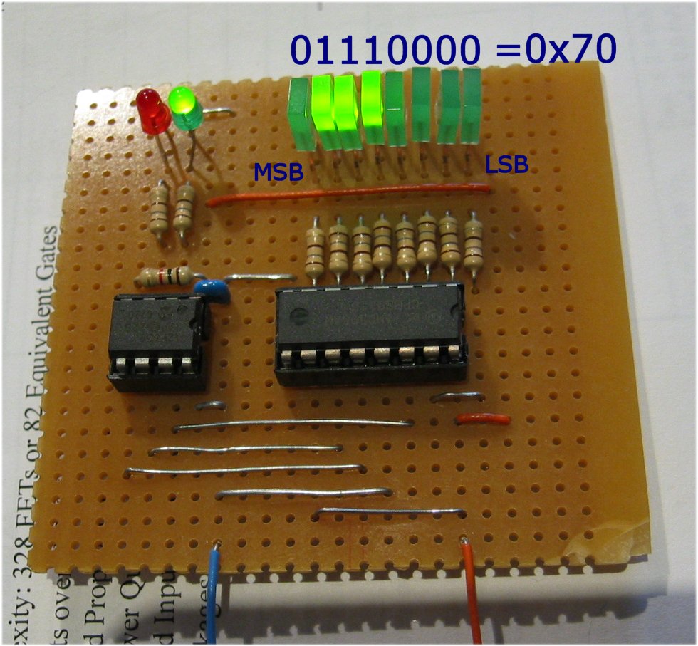
The photo below shows a PIC
being tested with a good calibration word.
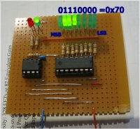
The actual calibration
value is displayed in binary on the 8 LEDs. The calibration value is unique to each PIC so the
devices you test will probably show a different value to this
example. If you're having
programmer trouble then I suggest you look at the Microchip
PICkit2 programmer, or a hardware clone of the same. The
Microchip software used with this programmer makes erasing the
calibration word by accident almost impossible. If you do erase it
then it also makes fixing the problem easy too! |
|
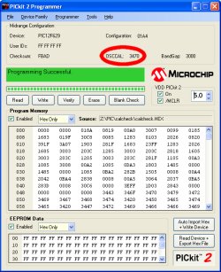
Screendump of the same
PIC being programmed with the test code in my PICkit2
programmer. You can see the PICkit2 software has read
the OSSCAL word from the PIC (circled red).
34 is the RETLW
instruction and 70 is the
value being returned.
|
|