|
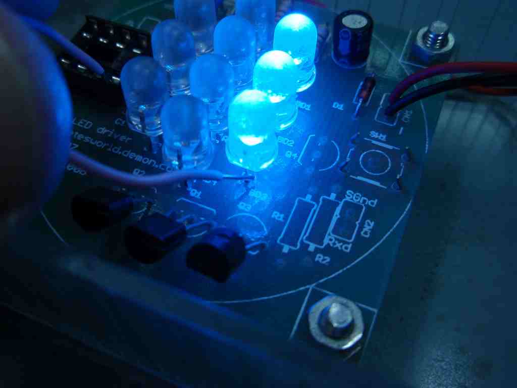
RGB LED PWM Driver Troubleshooting Before starting these checks, disconnect the power to the board and remove the PIC from the socket. Store it carefully. Are you using a 12 volt regulated DC power supply? If not you need to obtain the correct power supply before testing further. Connect the external 12 Volt DC regulated power supply to the circuit. Once the PIC has been removed from the
socket, there is nothing driving the MOSFET transistors so the LEDs
may turn on/off or flicker. This is normal. |
|||
| Power
Supply Test Step 1 Measure the output voltage from the Power Supply without having it connected to the circuit. This should be about 12 volts (11.8 to 12.8 volts is acceptable) Step 2
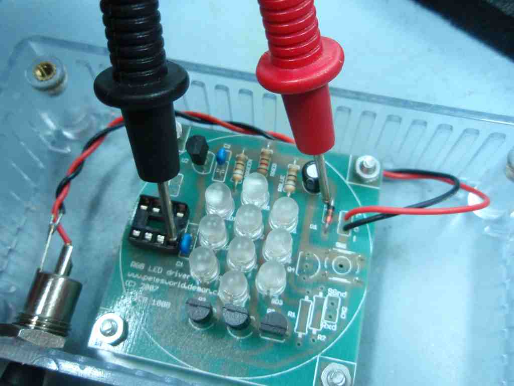
Measure the voltage between Ground and the 12 volt supply at the cathode end of D1. (pin 8 of the IC socket is at Ground this is a good place to measure from) This should be >11.2 volts, if it is goto Step 2. If it is not then possible causes are:
Step 2
Measure the 5 volt supply between pins 1 and 8 at the IC socket. Pin1 should be +5 Volts relative to Pin8 (Ground) Between 4.8 and 5.2 volts is acceptable If it is not then possible causes are:
|
|||
LED Test |
|||
 |
 |
 |
|
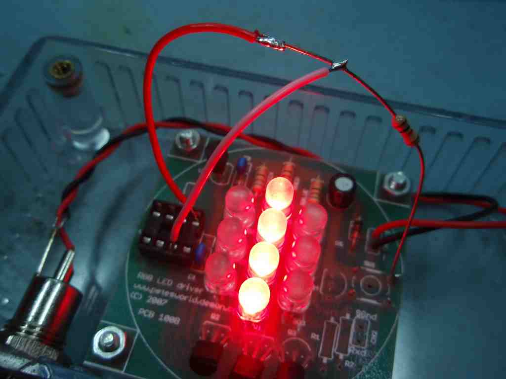
| Test each
column of LEDs by connecting the cathode of the LED nearest the
MOSFET transistors to Ground. You do not need to remove the MOSFETs
to carry out this test. DO NOT attempt to test other LEDs in the column by grounding their respective cathode (you may damage or destroy the LEDs even if they had been working) The LEDs should light when the cathode is connected to ground If they do not light and there is >11.2 volts at D1 then possible causes are:
|
|||
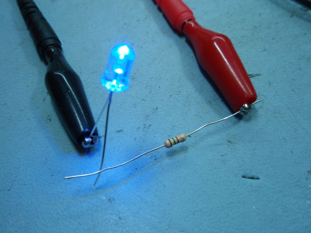
| MOSFET
Transistor Test
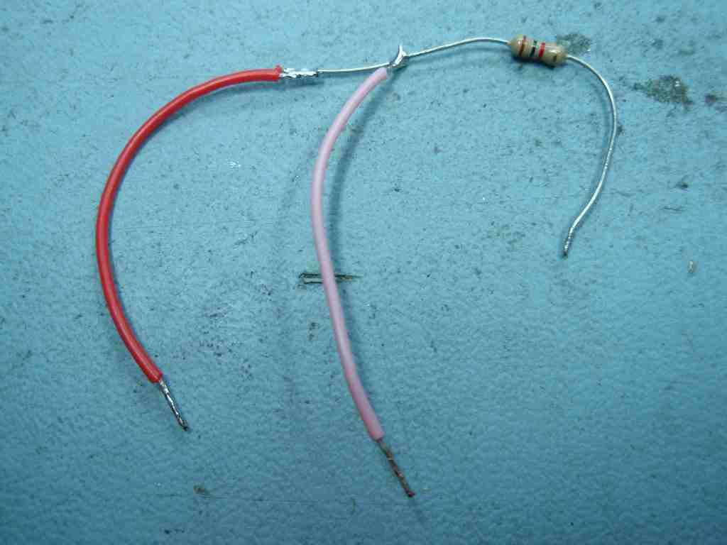
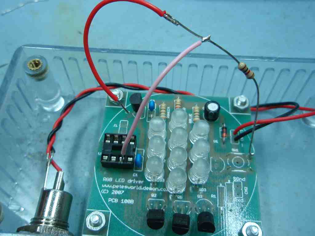
Make up a test lead as shown above. I used a 1Kohm resistor; you can use any value from 100ohms to 33Kohms, it's not critical Solder the free end of the resistor to Ground, a good place to pick this up is the lead of the switch SW1 as shown below. |
|||
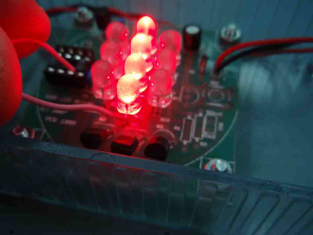
| Turn
Off Test
|
Turn
On Test
|
||
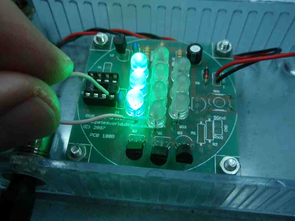
|
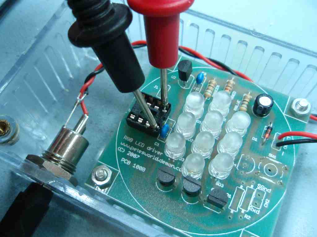
Leave the red wire disconnected. Touch the pink wire onto the IC socket pins 5,6 and 7, corresponding to the Blue, Green and Red LED columns. If the LEDs are on, they should turn off when the wire is touched on the pin, if they are off they should remain off. If one or more LED columns remain on when this test is carried out possible causes are: a) short between the source and drain terminals or drain and ground. Check solder joints as the leads of the MOSFET are close together and you may have a solder bridge. b) the respective MOSFET has failed and needs replacing. This mode of failure is normally caused by static discharge on the MOSFET gate terminal damaging the gate insulation. Be sure to take proper antistatic handling precaution when replacing it.
|
If the LEDs passed the Turn Off Test
you can carry out the Turn On Test Connect the red wire to +5 volts. Pin 1 of the IC socket is at 5 volts so use this. Now repeat the previous step touching the pink wire on to pins 5,6 and 7. Each LED column should light as the corresponding pin is touched. (make sure the red wire remains connected to +5 volts). If they remain on after you touched the pin, you can go back to the previous step and you should be able to turn them off again If one or more columns does not turn on AND the LEDs worked when the LED Test was carried out then the corresponding MOSFET has failed. |
||
Identifying the LED cathode and anode terminals / Testing LEDs out of circuit |
|||
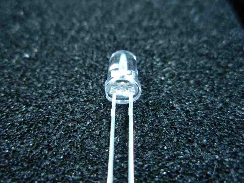 The cathode is normally denoted by a flat on the body of the LED. I have seen LEDs (bought on eBay) where this is not the case so it is worth testing one LED of each colour to verify it.
To check which lead of the LED is the cathode use a 150ohm resistor in series with LED and connect to a 5 volt test voltage. When the LED lights, the lead connected to the negative end of the 5 volt supply is the cathode. If the LED doesn't light either way round it is most likely faulty. Test other LEDs to make sure the test circuit is working before discarding it.
|
|||