Practical PIC Projects


Simple RS232 to
 logic level converter

for PIC micros / TTL / CMOS


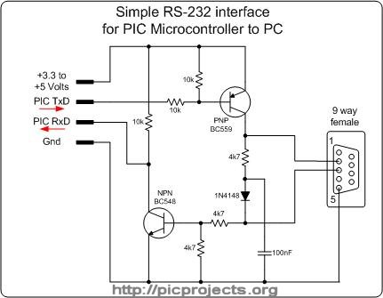
The circuit shown will convert logic level voltages to and from RS232 serial voltages levels.

For basic serial comms between a Microchip PIC and a PC or other device you generally only need to connect the Gnd, Txd and Rxd lines.

This little circuit will work with a supply voltage of 3.3v to 5v making it ideal for interfacing with a PIC 

It derives the negative supply for the RS232 transmit data from the serial RS232 receive data line in a parasitic fashion.  This means that the device it's connected to must use voltage levels within the RS232 specification. You can't for example connect two of these back to back since nothing is supplying the negative voltage.

The RS232 physical specification gives a logic 1 at the receiver input as -3 to -25 volts and logic 0 as +3 to +25 volts.  You may find that the reliable transmission over long cables, especially in electrically noisy environments with a 3.3v supply is not possible.

We've successfully used this circuit to transfer a 1.6Mb Linux kernel to a router at 115Kbs using a 3.3 volt supply without any errors through several metres of cable.

Note: If you have problems receiving data try swapping the 100nF capacitor for a 47nF.

Schematic in PDF format

Similar designs to this appear on various websites on the Internet and I believe the original design appears in AN-681 from National Semiconductor, 1990 


The circuit is so simple you can construct it on some strip board, or even wire it up ' birds nest' fashion. However, for a professional job I've done a PCB layout for it because it's quite a useful adapter to have around.

On the 4-pin connector the signals are:

  1.    +3.3 to +5 volt supply
  2.    Transmit data from PIC
  3.     Receive data to PIC
  4.     Supply Ground

On the 9-way D-connector the connections are:

   2.     RS232 transmit data out
   3.     RS232 receive data in
   5.     Signal Ground

A component overlay is shown above. The original artwork is available here as an Eagle PCB CAD .brd file and also in PDF format.

The layout is designed for 1/8 watt resistors - these are a bit smaller than the standard 1/4 watt parts.  You can use 1/4 watt resistors but you'll need to stand them on end.


Here's a couple of photo's of a completed board. Note the very small 1/8 watt resistors. 

Also notice the blue jumper on the 4-way connector. This shorts the RxD and TxD signals together forming a loop-back for testing 

Hook the board up to a suitable power supply, then connect to a PC running a terminal emulator. With the loop-back in place anything you type at the terminal should be echoed back.

(click on images for large version)