Recently I got a new motorbike
and on my second trip out, with only 50 miles on the clock the
rectifier/regulator unit failed. The battery on a bike is
pretty small and with the head light permanently on and all the
ECU, ignition and fuel injection stuff it didn't take long to
run the battery flat. Fortunately I'd stopped and there
wasn't enough charge left to turn the engine over, but it's
possible for the battery to discharge and the bike to cut-out
while riding - not good.
After a bit of research it
became apparent that this type of failure is common, with the
regulator either not charging the bikes battery, or overcharging
it. Despite the ECU monitoring the voltage it doesn't
generate any indication of a low voltage condition to alert the
rider.
This project aims to provide
the rider with an early warning of a fault to the bikes
battery/charging system by connecting to
the electrical supply on the bike and continually measuring the
voltage. If it goes outside of programmed set points it
alerts the rider by activating an LED.
The design can be
applied to cars as well as motorbikes and could also be used for
other voltage monitoring applications.
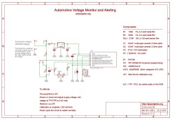
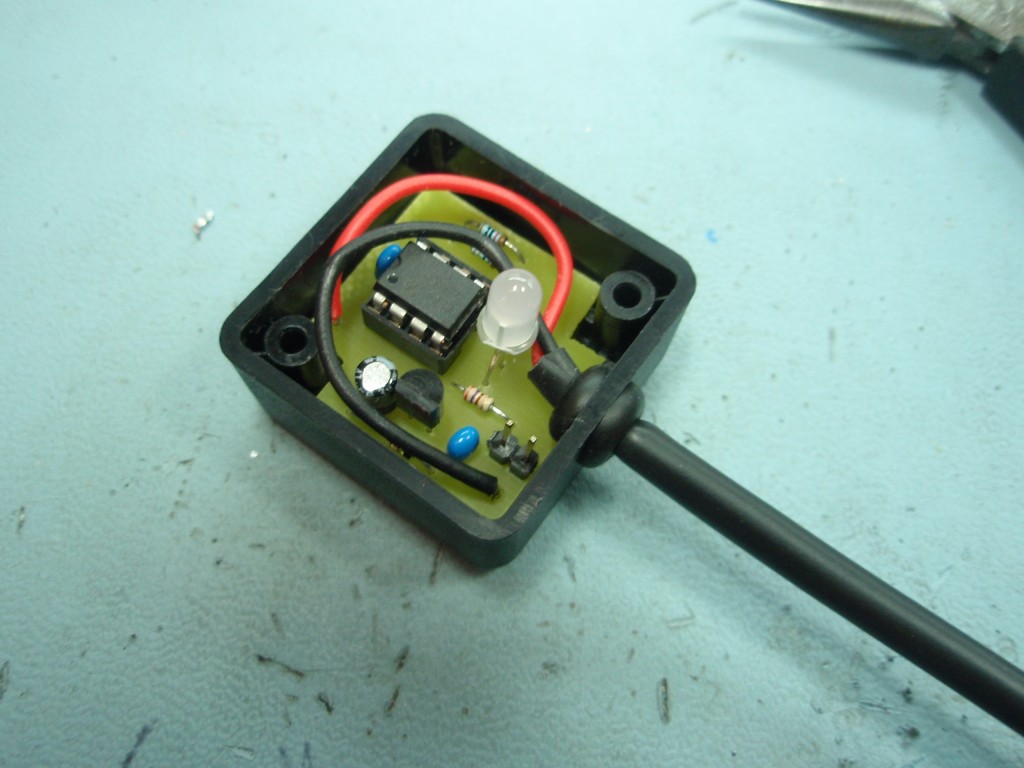
Hardware
The circuit use a
PIC12F683
microcontroller
programmed with firmware (see download section) that measures the
vehicle supply voltage using an Analogue to Digital Converter
(ADC) and compares it to set voltage points,
activating the bi-colour LED to alert the rider when the
voltage goes outside the expected normal operating range.
The vehicle supply voltage
feeds IC2, an
LM2931AC-5.0,
Low Drop Out (LDO) voltage regulator IC to power the
microcontroller. This part is
designed for use in automotive applications and can withstand
load dumps and reverse transient. There are
several variants of this part, so make sure to get the 'AZ' or
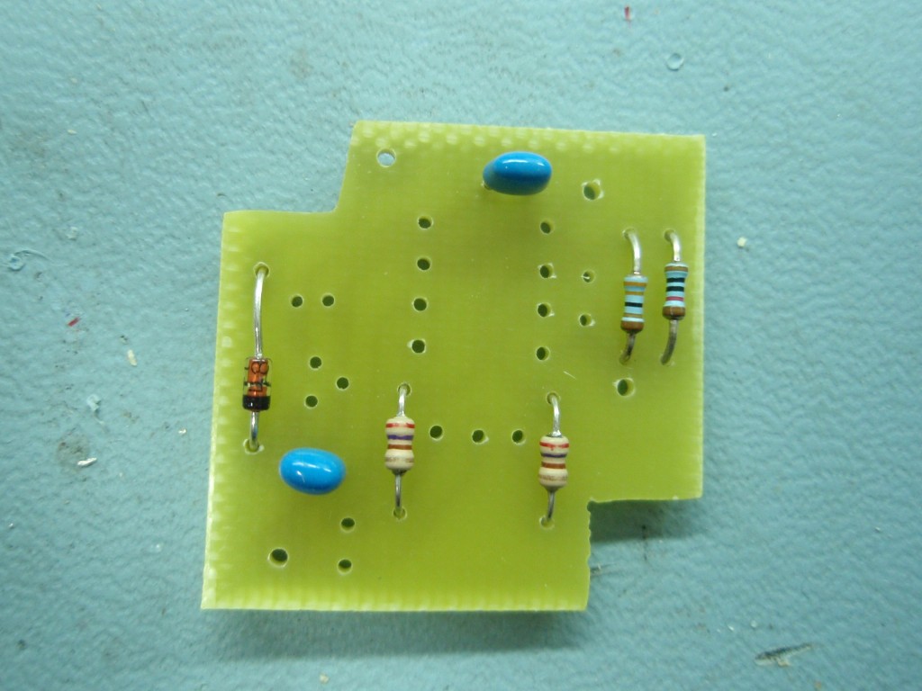
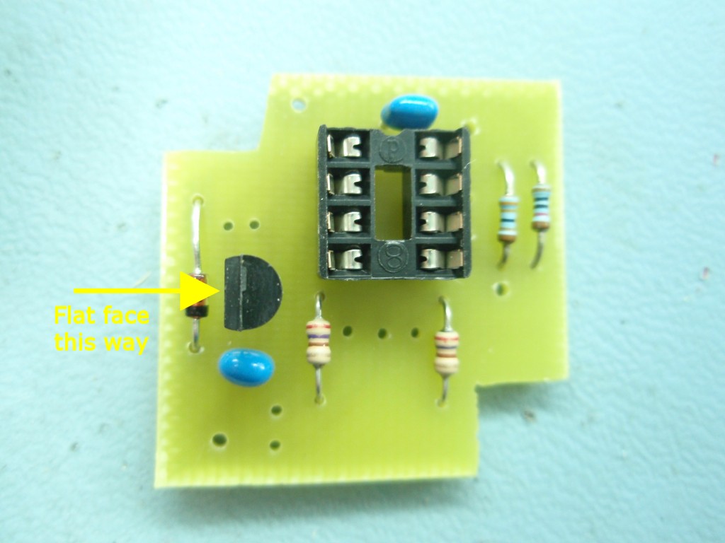
'AC' variant as these have a +/-3.8% or 2.5% tolerance output. Diode D1 protects the circuit
from accidental reverse polarity of the input supply
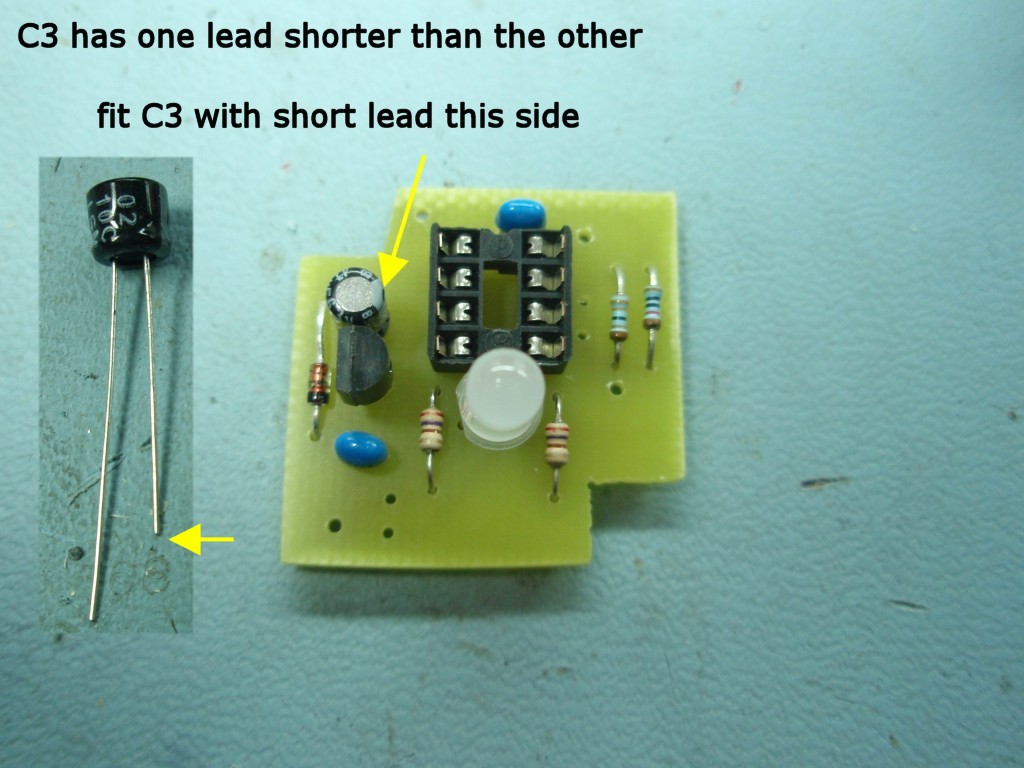
voltage. Capacitors C2
and C3
are required to stabilise the regulator as per the datasheet for
the device. The design uses a 47µF
capacitor
for C3, but a 22µF
part can also be used.
 The LM2931 was chosen because it is
designed for use on automotive electrical systems where the
electrical supply is quite hostile. For other applications
the following devices could be used as an alternative to the
LM2931.
The LM2931 was chosen because it is
designed for use on automotive electrical systems where the
electrical supply is quite hostile. For other applications
the following devices could be used as an alternative to the
LM2931.
An LM78L05
is cheap and easy to find, it's not ideal but should
work. If you do use it, you can omit C3, but will need to
replace C2 with a 1µF / 25 volt electrolytic.
For a
precision 5 volt LDO regulator look at the
LP2950CZ-5.0, this will need a 1µF / 25 volt
electrolytic capacitor for C2 and 1µF / 6.3 volt or 10 volt
electrolytic for C3.
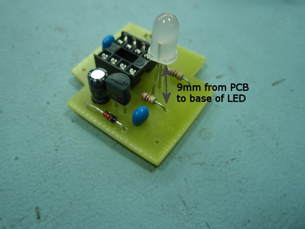
The status LED is a 5mm bi-colour
common cathode part, We used an HLMP4000 part although any bi-colour LED
should work here. It should have a milky white or defused body since
it needs to 'mix' the red and green to get orange. Clear LEDs don't do this so well.
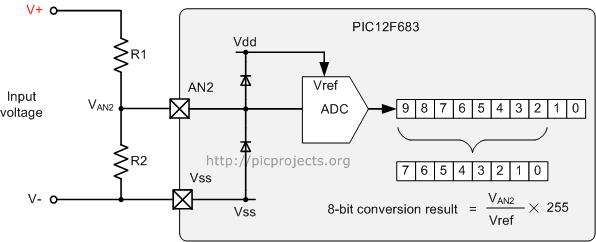
The PIC12F683 contains a 10-bit
internal Analogue to Digital Converter (ADC) that compares the
voltage on the AN2 input (Pin 5) with a reference voltage.
This design uses the Vdd 5 volt supply to the PIC as the
reference voltage (Vref).
Since the range of voltages in a 12
volt automotive system can go up to about 15 volts, and higher
if the alternator regulator fails the input voltage needs to be
scaled down so it falls within the range 0 to 5 volts when
presented to the PIC. This is done using a voltage divider
comprising R1/R2 which are 1% precision resistors to help with
accuracy. There is an optional capacitor
C4 which can be used to filter the input, however this isn't
used here.
Should the supply voltage
exceed 20.16 volts the output from voltage divider R1/R2 will
exceed 5 volts. The PIC has internal clamp diodes on
the inputs connected to Vdd and Vss, the excess voltage will be clamped by the
diode while resistor R1 limits current to just a few milliamps.
Software
The software code the PIC is
running only uses the high order 8 bits of the 10 bit ADC
conversion result. The resolution of the ADC using
8 bits is 5 volts / 255 = 0.0196 volts/bit
(n.b. the firmware actually
checks the 9th bit of the result and uses it to round up/down
the 8-bit result)
The values of R1 and R2 are 10K0 and 3K30 respectively.
This gives a voltage divider ratio of
3K30 / (3K30 + 10K0) == 3300 / 13300 = 0.248
(1:4.03)
Since we are scaling the input
voltage the minimum resolution of the measured input voltage is:
0.0196 / 0.248 = 0.07 volts
So as an example if we have an input voltage
of 12 volts, the output voltage at the junction of R1/R2 seen by
the PICs ADC input will be 12 x 0.248 = 2.977 volts.
The ADC will convert this to a
numeric value which is calculated as ( Vadc / Vref ) x 255
( 2.977 / 5.0 ) x 255 = 152
The maximum voltage we can
measure using a 5 volt reference and 10K0/3K30 divider is:
5 volts / 0.248 = 20.16 volts.
The software program measures
the input voltage around 8 times per second and keeps a rolling
average of the last 8 measurements. The averaged value is compared to
preset values which are used to determine the battery voltage
state indicated by the status LED.
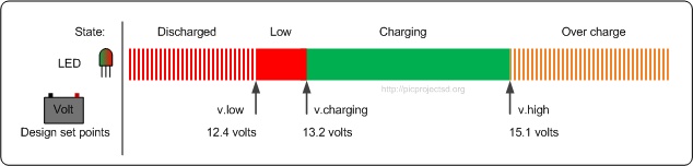
above 15.1 volts
the LED flashes orange ( red+green mixes to give orange)
between 15.1 and 13.2 volts, the LED
is steady green
between 13.2 and 12.4 volts, the LED is steady red
below 12.4 volts, the LED flashes red
The software applies 1 bit (0.07 volts) of hysteresis to these set points.
With a good battery when the
ignition is first turned on the battery should be in the 'low'
voltage range since the engine isn't running the battery isn't
being charged. Once the engine is started the output from
the alternator should bring the battery voltage into the
'charging' range. If it doesn't stay in the charging range
this will be indicated by the LED and should be investigated.
These set points are stored in
the PICs EEPROM and can, if required, be modified either by
editing the EEPROM directly or in the source code.
The value returned by the ADC
for a given input voltage can be calculated using the following:
Set
Point Voltage * (R2 / (R1+R2))
/ (Vref / 255) = ADC Value
Set
Point Voltage * (3.3 /
(10+3.3)) / (5 / 255) =
ADC Value
Example:
14.5 volts x
0.248 / 0.01961 = 183
(hexadecimal 0xB7)
Status LED Mode
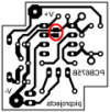
While the voltage remains
within the charging voltage range, the green LED will turn off
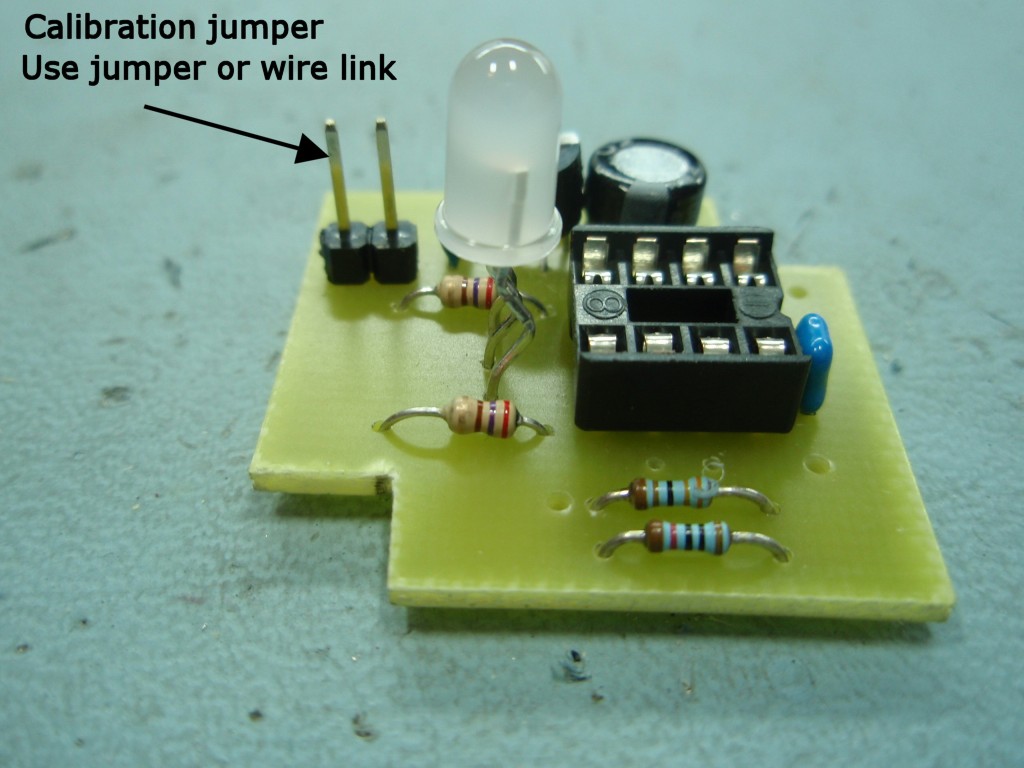
after approximately 15 seconds. If you want the LED to
remain on continually connect GPIO5 (pin 2) to ground. On
the PCB there are two pads which can be bridged with a solder
blob to ground this pin (circled red, see image right)
Calibration
The values of the three design set points are calculated based
on the resistors R1 and R2 being exactly 10K0 and 3K30 ohms and
the voltage reference exactly 5.00 volts. In the
real circuit the resistors are only accurate to within 1% and
the LM2931 accurate to +/-3.8% so the firmware needs a one-time calibration before use.
This is done by fitting JP1 then powering up the circuit from a
variable power supply. The variable power supply is
adjusted until the voltage measured at the input to the ADC (pin
5) using a precision voltmeter is exactly 2.50 volts. Once set, the jumper is removed
and the PIC calculates and saves a correction multiplier. The
multiplier value is then applied to the set points during normal
operation.
Summary
1. Fit jumper / link between GPIO4 (pin3) and Gnd.
2. Power circuit up using variable output PSU.
3 Adjust board supply voltage until voltage at AN2 (pin 5)
is exactly 2.50 volts.
4. Cut/open jumper on GPIO4 (pin 3).
5. The Status LED will flash to show the 9 bit calibration
value
This repeats until reset/power cycled
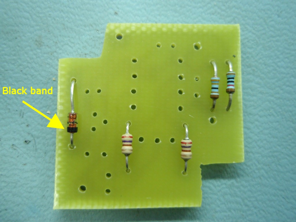
Read
as MSB to LSB, Red =0, Green = 1, Orange =end
This repeats until reset
or power cycled.

This is for information only and you don't need to do
anything with this.
6. Remove power to circuit and reapply (or reset PIC).
You can do the calibration as many times as you want so if
you mess up, or just want to have dummy run you can. Just
repeat steps 1-6 each time you need to calibrate it.