|
8
Channel PWM LED Chaser
for 16F628A
(Kit 481)
|
 |
Description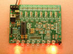
Update:
Variable chase speed option (see here for details)
This neat little circuit provides 8 LEDs
directly driven from the PIC along with a single mode control switch. The
firmware elsewhere on this page drives the LEDs with a
5 bit PWM signal providing each of the 8 LED channels with four
levels of intensity; off, dim, mid, bright.
A number of sequences are programmed into the firmware to
provide some interesting visual effects and chase sequences,
including the classic effect seen on the car in the
Knight Rider TV series.
The software has sequential, random and manual sequence run
modes and manual advance to the next sequence in any mode.
The selected sequence and mode are also saved to non-volatile
memory so it will always restart in the selected mode.
The design is deliberately
simple with each LED being directly driven from a PIC I/O pin.
This and the inclusion of an in-circuit programming header (ICSP)
make the circuit ideal for teaching/learning introductory PIC
assembly language programming.
You can use it with different
sized LEDs and mixed colours, as well as fewer than 8 LEDs.
As well as using it as a LED chaser it is great for adding
effects to toys and models. See FAQ
However, if you just want a
cool LED chaser without having to write any code, a ready
written LED chaser program including 34 chase effects with source code and
programmer ready HEX files is provided at the bottom of this page.
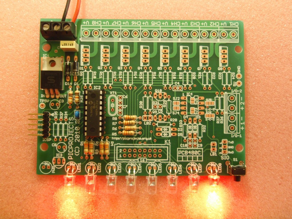
The circuit has been
constructed on a PCB but can easily be built on strip-board or a solderless breadboard.
Need a board that can
drive more LEDs? check out the
Power MOSFET Chaser Project
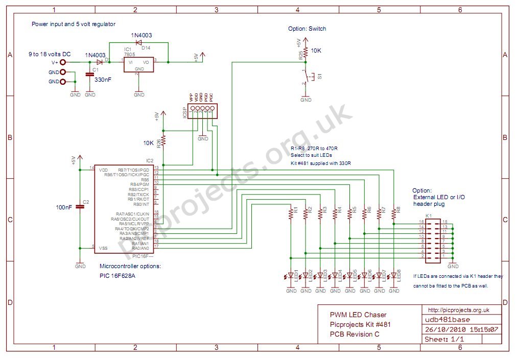
Schematic
Download
schematic in PDF

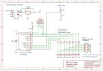
Circuit Description
The heart of the LED chaser is
the PIC 16F628A microcontroller, IC2. The program that runs on this chip controls the LEDs
attached to the output port pins. Resistors R1 thru R8
limit the current through LED1 - LED8 to a safe level that
won't damage the PICs I/O ports or LEDs. The LEDs can
either be mounted on the PCB or via header plug K1 and a ribbon
cable which permits the LEDs to be mounted in a different
arrangement, location etc. If the LEDs are connected via
the K1 header, don't install LEDs on the PCB, it's either or but
not both.
Resistor R25
provides a pull-up for the input connected to switch S1.
R26 pulls up the PIC's MCLR reset signal during normal operation
while allowing the input to be raised to 12.5 volts during
in-circuit programming. The ICSP header provides connection for an ICSP programmer such as a PICkit2 making it easy to reprogram
the PIC without removing it from the PCB.
Capacitor C2 is used to
decouple the 5 volt power supply to the PIC. If you're building the
circuit on a breadboard or stripboard you should ensure it is
located close to the PICs Vdd connection (pin 14 ).
Power is supplied to the
circuit through the 3-way terminal block and must be smooth DC between 9 and 18 volts.
The PIC requires a precisely
controlled 5 volt supply and this is provided by IC1, a 7805
3-terminal, 5 volt regulator. Typical current drawn by the
circuit with all LEDs on is only around 100mA so the voltage
regulator doesn't require any additional heatsink. Capacitors C1
stabilize the regulator. Diode D1 protects the circuit from
accidental reverse polarity of the input voltage. Diode
D14 protects the regulator and is only really needed if you will
be using the ICSP feature (doesn't hurt to fit it anyway)
Additional
information about PCB480C
Notes:
- The latest
high brightness LEDs are very bright even with 330R current
limiting resistors. However, if you do need to change these resistors
for some reason take into account the maximum current
that the PIC can source from an I/O port pin is 25mA, and
also be aware that the output voltage will drop as you
increase the load. Ideally keep the current per output under
15mA
- If you install LEDs
that require a lower value series resistor you may find you
are unable to program the PIC in-circuit via the ICSP
header. This is because the I/O port pins on the PIC
that are used for In-Circuit Serial Programming are shared with the LEDs. The programmer may be unable to drive these
lines when lower value resistor are used. With the
330R resistors and PICKit2 programmer, In-Circuit
programming should work without problems.
- The ICSP header
allows programming of the PIC while installed in the
circuit. It is only required if you intend to
connect a programmer to modify the sequences or code.
It is not supplied with the kit but is available as an
option.
Component List
- Diodes D1 and D14 are
shown as 1N4003. Any 1N400x series diode can be used
here.
- S1 is a 6mm right angle
tactile switch, Omron B3F series.
Rapid Electronics part # 78-0140
cheaper alternative is Rapid Electronics part # 78-1154
- IC1 is a 7805, 5 volt, 1
amp regulator IC.
For use in automotive applications, or where you need the
circuit to operate from input voltages down to 6 volts
replace IC1 with an LM2940CT-5 and install a 47µF/10V
to C3
Rapid Electronics part # 82-0678 and part # 11-0815 or
11-1502
- 3-way terminal block is
5.08mm pitch but a 5mm part will also fit.
- The PIC16F628A needs to be
programmed with the correct firmware (see
firmware section). If you bought the kit this code is already programmed into it.
- C1 is 5mm polyester box
type
- C2 is 2.5mm radial lead
multilayer ceramic Y5V or X7R dielectric
- Resistors are all 1/4
watt, 5% carbon film type.
All components used in this kit can be sourced from
Rapid
Electronics
Standard parts are used in
this project and should be easy to source from distributors
world wide.
Power Supply
The circuit requires a 9 to 18
volt DC power supply. The board draws under 100mA during
normal operation. Power supplies rated for 250mA or
greater with an output voltage in the ranged 9-18 volts DC
should be suitable for use with the project.
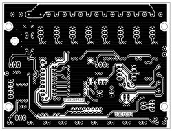
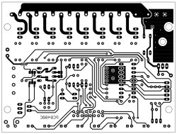
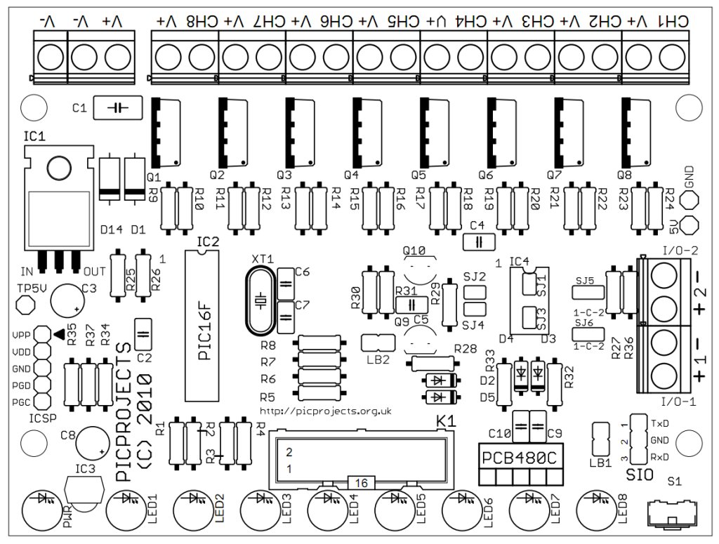
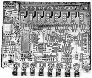
PCB Artwork
The PCB is available to buy
from the Picprojects online store. This a quality double
sided, thru-plated board with solder masks and component overlay
on FR4 board with RoHS compliant OSP finish to the copper.
The artwork is provided if you want to etch your own board,
however it is a double sided board and unless you can
thru-plate the holes it will be difficult to solder both sides
of some components such as the terminal blocks.
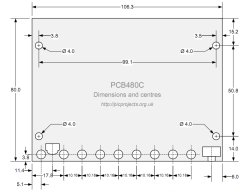
Physical dimensions and
centres
Construction notes:
 Illustrated guide to assembling the kit. Please
read through the whole of this section before starting
assembly and refer back to it during assembly.
Illustrated guide to assembling the kit. Please
read through the whole of this section before starting
assembly and refer back to it during assembly. |
click on the photo's for
large version
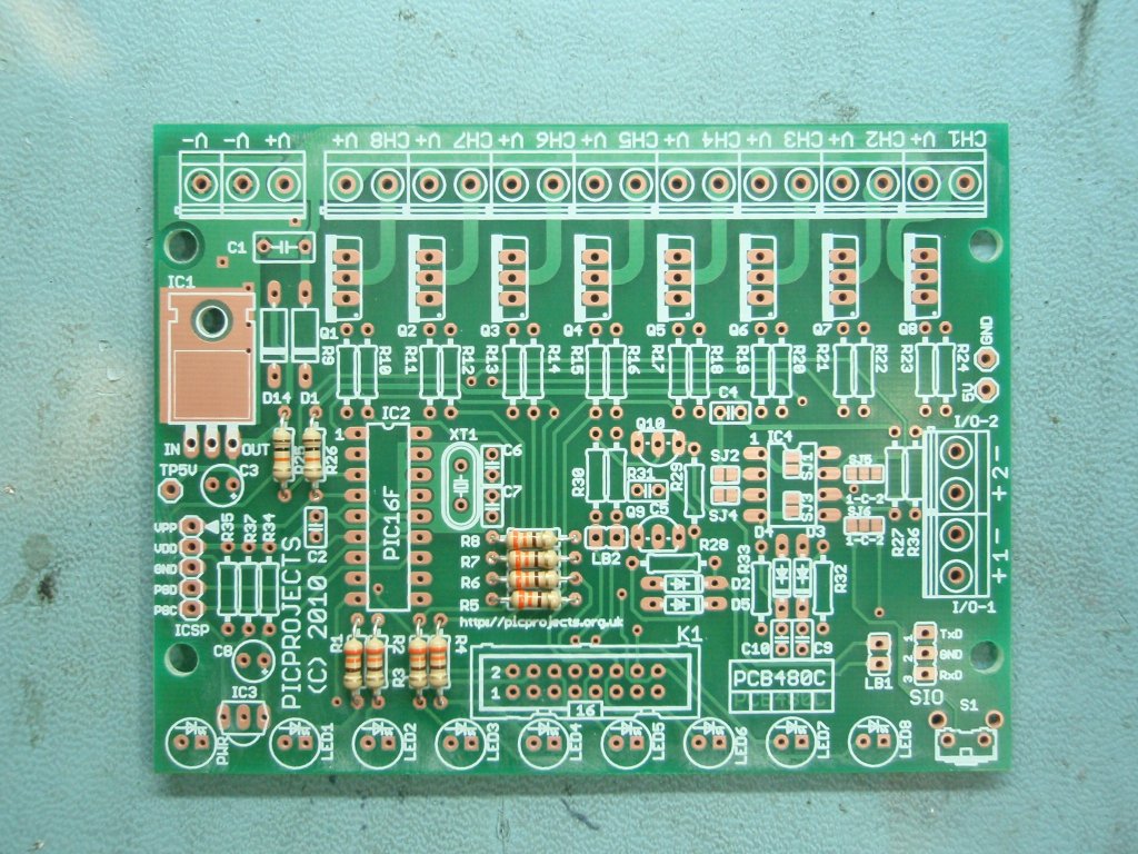
Step 1. Install the
resistors. The coloured bands denote the resistance value
as shown below. Fit the resistors into the correct
location on the PCB. It doesn't matter which way round they
are oriented.
 brown, black, orange, gold - 10K (R25, R26)
 orange, orange, brown, gold - 330R (R1-R8)
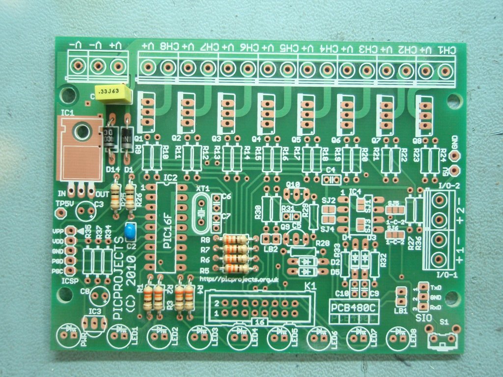
Step 2. Fit the
two 1N4003 diodes. These have a silver band at one end of
the body and must be fitted the correct way round as shown.
Step 3. Install the two
capacitors C1 and C2. Since they are physically different
you can't mix them up and it doesn't matter which way they are
oriented when fitting to the PCB
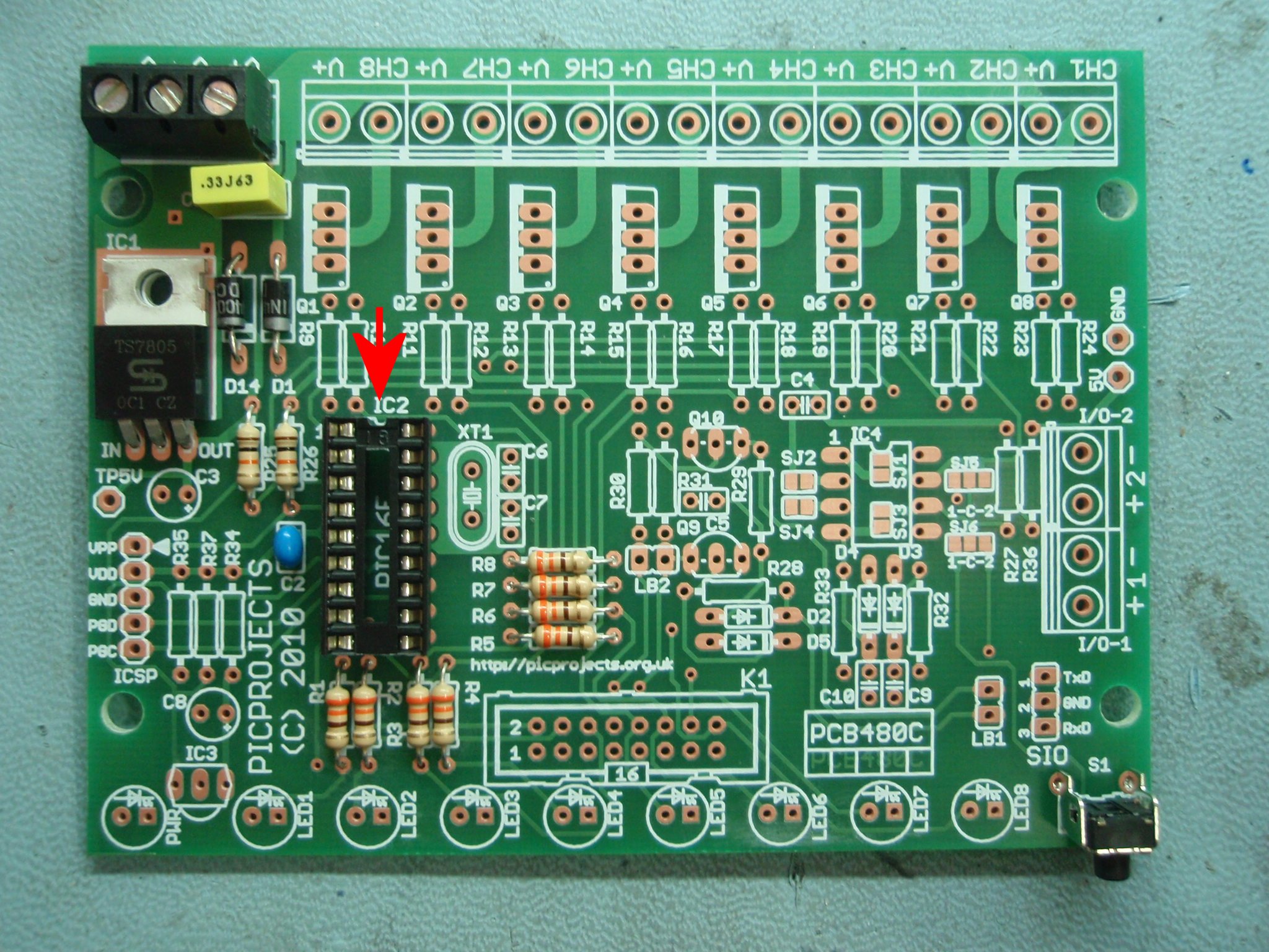
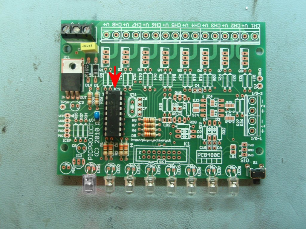
Step 4. Install
the socket for IC2. Note that it has a small indent at one
end, you should fit the socket with indent at the end arrowed in
the photo. Also install S1, the 7805 regulator IC1, and
the 3-way terminal block.
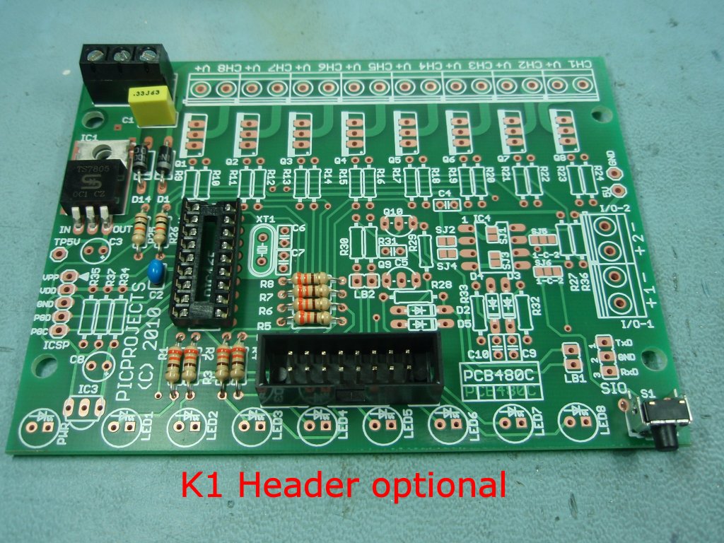
Step 5. [OPTION]
If you
intend to mount the LEDs off the PCB you can fit a 16 pin header
plug in position K1 on the PCB. This can be used with an IDC connector and ribbon cable to attach the LEDs. This allows the cable to be unplugged making
assembly easier and allowing different cable/LED combinations to
be swapped easily.
You can't install LEDs on the PCB AND use LEDs
connected to the header. It's either / or but not
both. The header isn't supplied in the kit but can be
bought as an option from the
on-line store
For more details on the K1
header plug and Octopus Cable
see here |
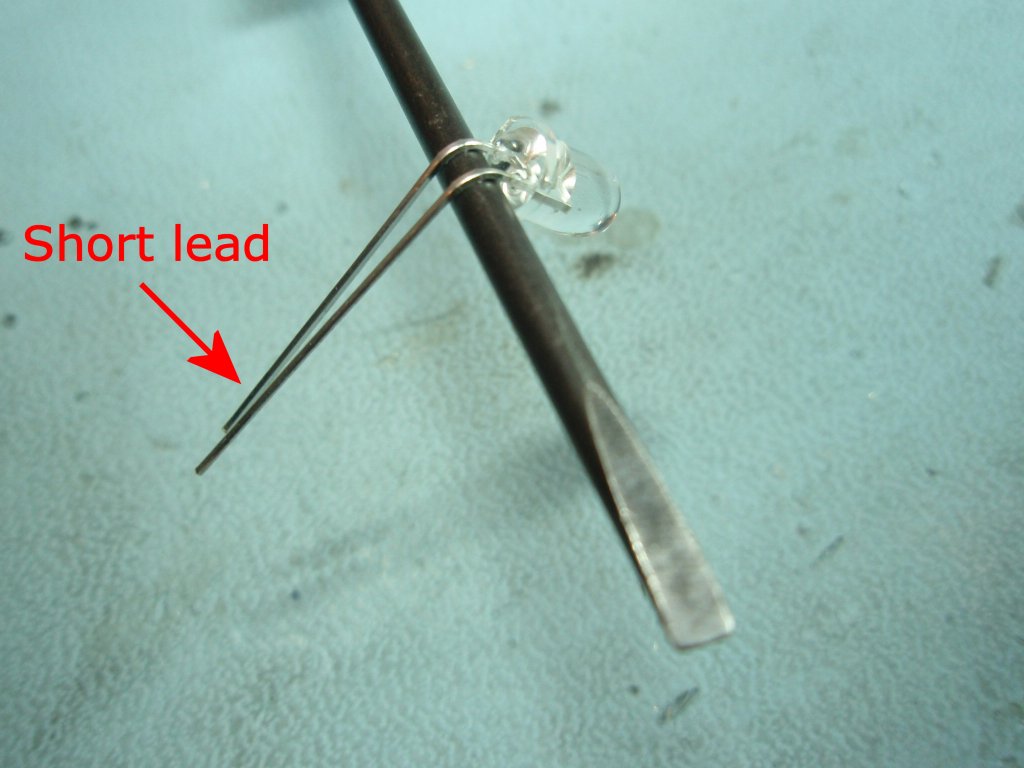
Step 6. When
fitting the LEDs to the PCB use a thin screwdriver to bend the
leads of the LED around through 90o in a curve.
One lead of the LED is shorter than the other.
This indicates the Cathode terminal of the LED. Ensure it
is positioned as shown otherwise it will be in the wrong
position to fit the PCB.
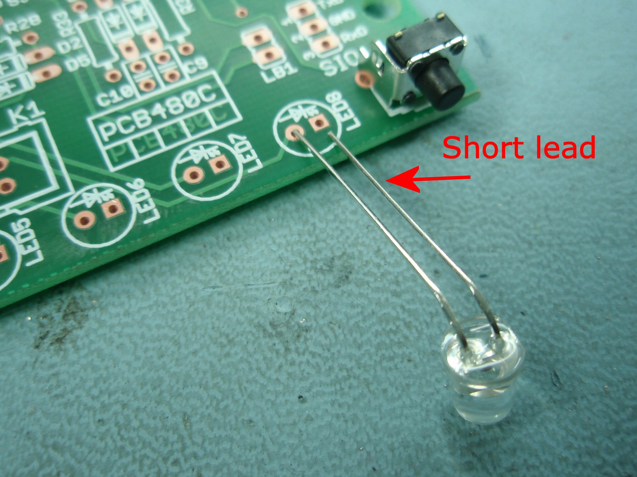
Step 7. Fit the
LEDs to the PCB with the short lead of each LED to the hole of
the square PCB pad.
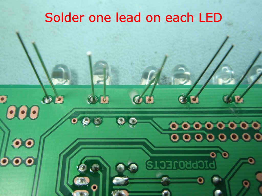
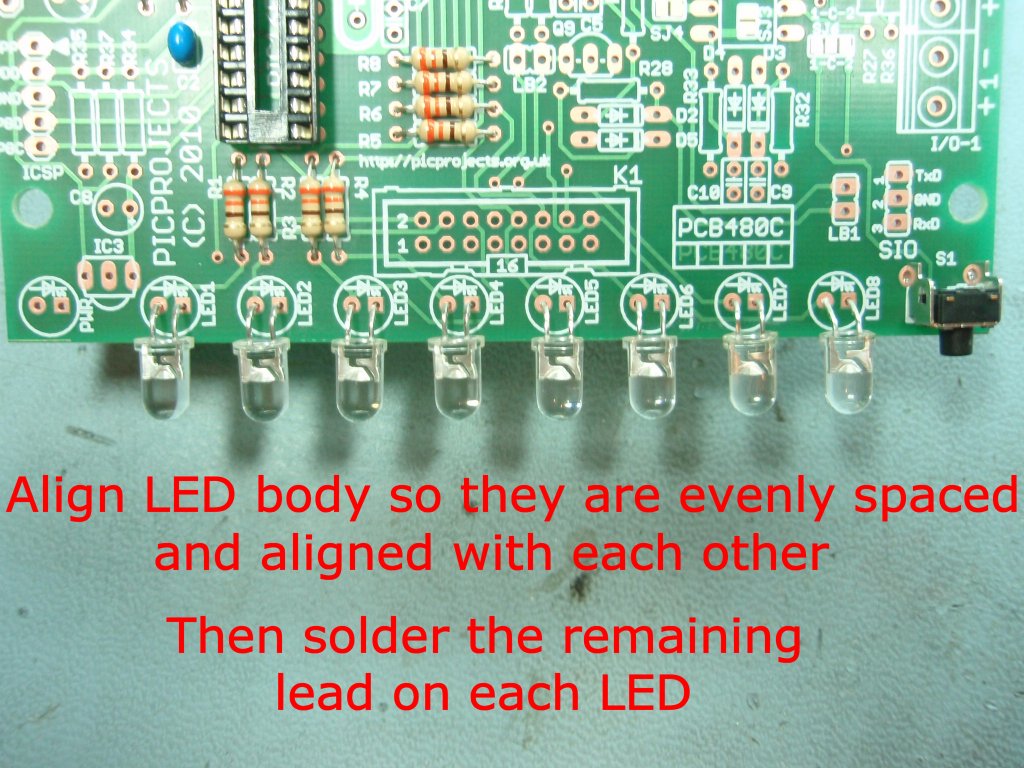
Step 8. Initially only
solder one lead of each LED as shown.
Step 9. Align the LEDs
so they are evenly spaced and when viewed horizontally form a
neat line. Once you have then aligned solder the remaining
leads of each LED.
At this point in the assembly.
- Check the PCB to
make sure solder joints are neat and there are no
solder bridges between pins.
- Make sure all
excess component leads have been neatly trimmed.
- Clear the work
area of any component lead off-cuts, solder splashes
etc.
|
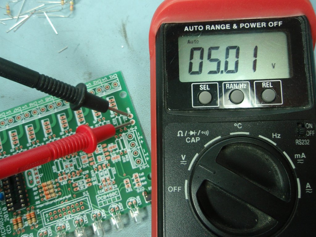
Step 10. Apply
power to the board. This should be 9-18 volts DC.
Connect the positive power lead to V+ on the 3-way terminal
block. Connect the negative or ground lead to either of
the V- connections on the 3-way terminal block.
Now using a multimeter check
the 5 volt supply is present and of the correct voltage.
A reading between 4.75 and 5.25 volts is acceptable. There
is a Gnd and 5 volt test point on the right side of the PCB (see
Step 10 photo)
If the voltage is NOT within the acceptable range you must resolve the cause before
continuing.
 Couple of points, should be obvious really but I'll
state it anyway:
Couple of points, should be obvious really but I'll
state it anyway:
- Do not insert or
remove the IC2 when power is applied to the board.
- Do not solder any
connections to or on the PCB while power is applied
|
Step 11. Disconnect
the power from the board. Now you can fit the PIC
microcontroller into the IC2 socket. You will see a small
dot and indent at one end of the body. This should be
fitted so it is towards the end arrowed in the photo.
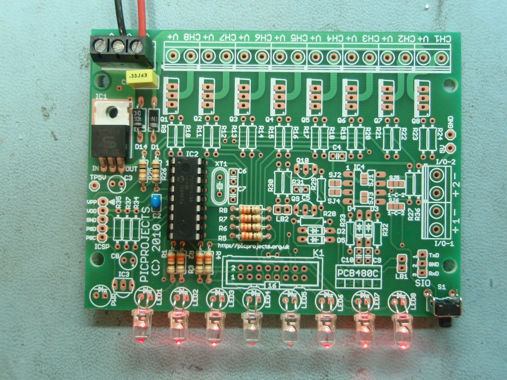
Step 12. Reconnect
power and turn on, the LEDs should now start to run the
sequencer patterns.
- Press and hold S1 to enter
setup mode.
- Press S1 to cycle through
the 3 modes.
- Press and hold S1 to exit
setup mode.
If everything is working
correctly, you're all done.
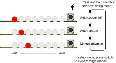
User Operation Guide
The program has three modes of
operation.
- Manual mode will run the
same sequence continually. When the switch is pressed it
will skip to the next sequence in program memory.
- In auto-sequential mode,
the program runs through each sequence in program memory
until it reaches the end of all defined sequences at which
point it restarts from the first one.
- In random mode the program
selects sequences randomly.
When the code is running in any
mode, a short press of the switch will make the controller skip
to the next sequence.
To enter setup mode, press and
hold the switch. Once it enters setup mode one of three
LEDs will light indicating the current run mode. A short
press of the switch cycles through the three modes. When the
desired run mode has been selected, press and hold the switch to
exit setup and return to run mode.
The current mode and selected
sequence are automatically saved to the PICs internal
non-volatile EEPROM memory 10 seconds after the last switch
press. When the LED chaser is next powered up it will load
and start running using the saved mode and sequence.
Update:
Variable chase speed option (see here for details)
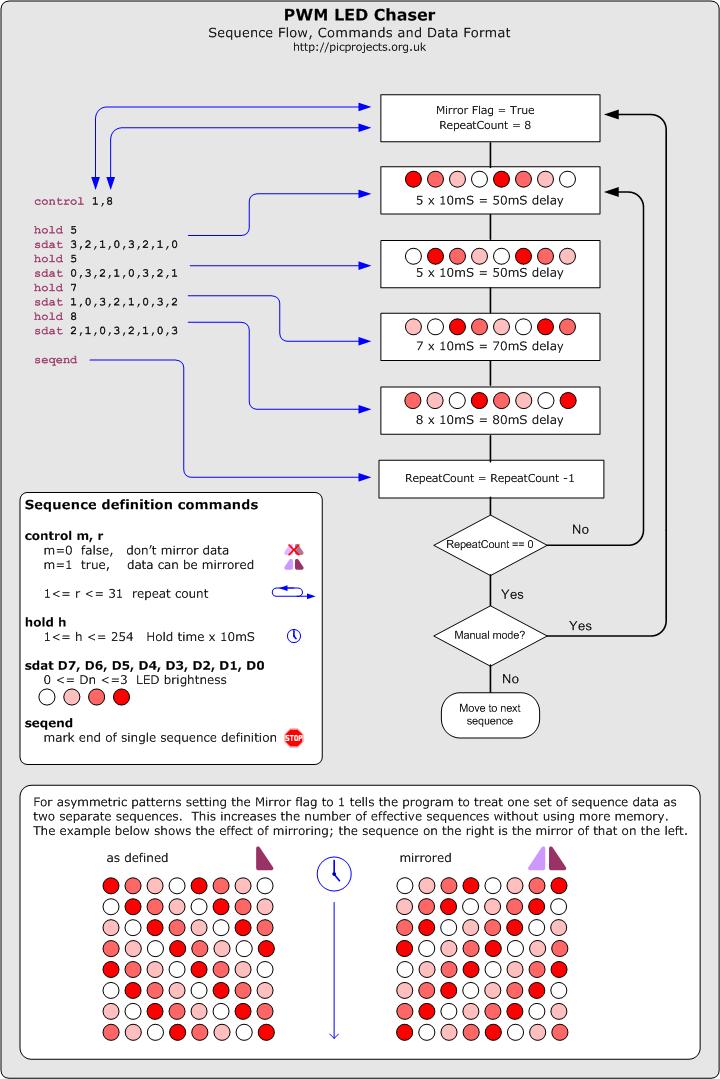
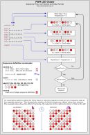
Description of Sequence Data
| The data
used to create the sequences is held in a separate
include file. You can add, remove or edit this
data to create your own chaser sequences.
To make the creation of
the data file easier a set of macros have been defined
which are used to create the sequence data. This
is described in the
Sequence data flowchart
(also available
as a JPEG image right)
If you download the
source code and look at the file named
pro418v3_SeqData.inc you can see the data used in the
project. You might want to edit this file as a
starting point to create some sequences of your own.
Notes:
- In manual mode,
when the repeat count reaches zero it will restart
the same sequence, to advance to the next sequence
press the switch.
- In Random mode it
will the select a random sequence number to run. If
the Mirror flag is true for that sequence it will
also randomly choose to mirror the data or not.
- In auto-sequential
mode if the Mirror flag is true it will run the
sequence and then repeat it with the data mirrored.
|
 |
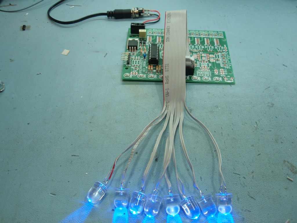
Octopus
Cable
Instead of mounting the LEDs on
the PCB, the K1 header plug allows a 16-way IDC socket and
ribbon cable to be assembled with LEDs as shown in photo 2.
The plug/socket makes it easy to disconnect the cable from the
board for assembly into a project, or enabling different
cable/LED assemblies to be used with one board.
If you are going to use the K1
header to connect LEDs using an Octopus cable you must not
install LEDs on the main PCB as well.
Photo 2 shows a cable made up
with 10mm blue LEDs and Photo 3 shows the board and LEDs
operating.
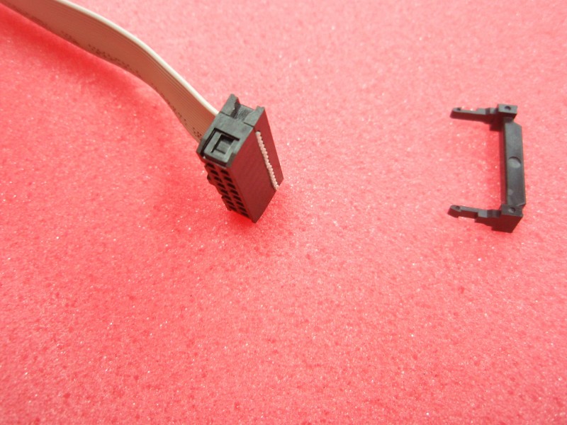
IDC Header Socket Assembly
This section shows you how to
assemble the 16 way header socket and cable to make an Octopus
cable. You can buy 300mm (12") of 16-way IDC cable and the IDC
header socket from the online shop
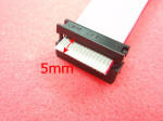
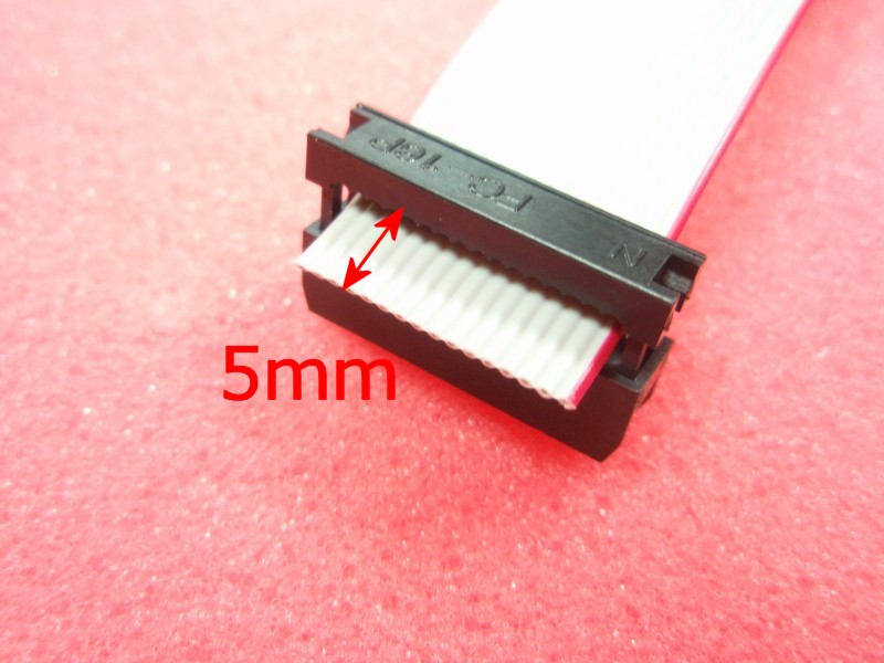
Photo 1 |
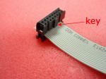
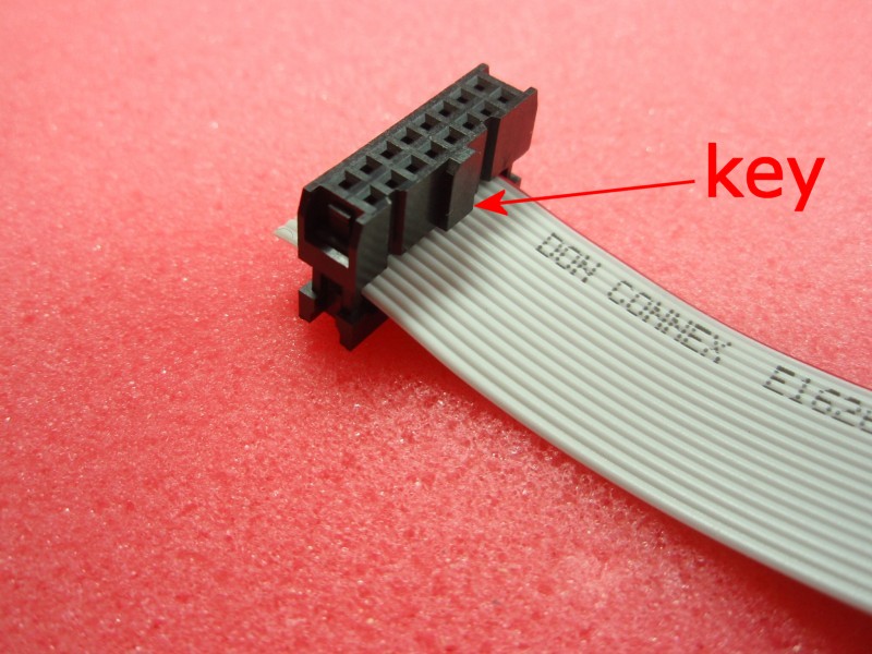
Photo 2 |
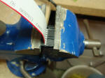
Photo 3 |
| Photo 1.
Insert the cable into the IDC header socket as shown.
Allow 5mm of cable through the header.
Photo 2. Ensure
the header key is on the side shown then press the two
parts of the header together with your fingers so the
cable is held in place. This is just to hold it
together; you're not trying to pierce the IDC cable
Photo 3. Place
the header and cable in a vice as shown. Make sure
the cable remains parallel with the connector assembly. |
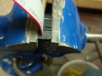
Photo 4 |
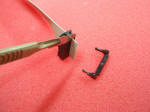
Photo 5 |

Photo 6 |
Photo 4.
Tighten the vice until the two halves of the header come
together. DO NOT CRUSH IT.
We're just using the vice to apply even pressure. Once
the connector halves meet the assembly is complete.
Giving it an extra
turn of the vice will only damage the plastic header.
If you haven't got a vice you can still clamp it by
pressing it together under a piece of wood, I've also
done it by shutting it in a door jam! The
important thing is to apply even pressure across the
whole width of the header.
Photo 5 + 6. Take a
sharp knife and trim the excess 5mm of cable. |
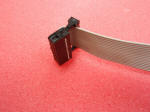
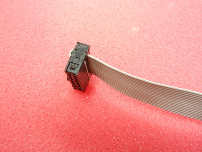
Photo 7 |

Photo 8 |
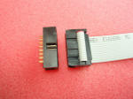
Photo 9 |
| Photo 7.
Pull the cable back over the top of the connector and
fit the strain relief clamp.
Photo 8. Press the
strain relief clamp into the connector by hand until it
locks in place
Photo 9. The
header and cable are now complete. The header fits
in to the PCB socket and is keyed to ensure it is fitted
the correct way round.
If you have assembled
the cable to the socket as shown above then the red wire
on the cable connects to header pin 1, the next wire in
connects to pin 2 and so on.
Refer to the
schematic for the connections to the K1 header |
Firmware
The PIC microcontroller
requires programming with the firmware which you can download
below.
The HEX files are ready to
program straight into the respective PIC chip. The latest
code version 2.0.7 supports the PIC 16F628/628A.
The Source code will allow you
to create your own sequences and then reassemble the code to use
them. Quick guide to
reassembling firmware using MPLAB
|
Description |
Filename |
Download link |
| |
|
|
| Source
code for 16F628A |
pro481v207.zip
V2.0.7 27/10/2010 |
 download
 |
HEX file
ready to program into the PIC.
Use with 16F628 / 16F628A only |
pro481v207.HEX
V2.0.7 27/10/2010 |
download
checksum 4994 |
|
Link to V3.0.0 Firmware |
|
|
Update:
Variable chase speed (see here for details)
If you need a PIC Programmer I
strongly recommend the
Microchip PICKit 2,
this is available from suppliers world wide or direct from
Microchip. It's reasonably cheap to buy and reliable.
I have a couple of them and I wouldn't use anything else now.
FAQ
Can you or
how can I make it run
more than 8 LEDs?
This is probably the most
frequent of the frequently asked questions :-)
The project is an 8 LED Chaser
and the firmware was written to work as an 8 LED chaser.
There is no quick and easy
change to make it a 9, 12 or some other number of LED chaser.
If you need a chaser with more LEDs then this project is not
suitable for your needs.
How can I add
more LEDs to each channel?
The basic LED chaser on this
page only works with single LEDs. If you need more LEDs on
each channel take a look at the PWM Power
LED Chaser project.
Will it work
with 3mm LEDs?
Yes, 3mm LEDs will work as will
8mm and 10mm LEDs. 3mm LEDs can be mounted on the PCB, 8mm
and 10mm LEDs would need to be connected by flying leads.
Can I use
less than 8 LEDs?
Yes, since the sequences are
user definable you can create sequences that use less than 8
LEDs.
I only want
it to run one sequence, can it do that?
Since the current mode and
selected sequence are saved to NVRAM, it always powers up in the
last mode and running the last sequence. Therefore if you
select manual mode and the sequence required, it will run only
that sequence until you change it.
Do the LEDs
have to be the same colour?
No they don't. If you
want you can mix different coloured LEDs. You can also mix
3mm/5mm/8mm/10mm LEDs if you want too.
Can you add
a button or potentiometer to change the speed?
Update:
Variable chase speed option kit now
available (see here for details)
The sequences don't have a
speed as such, the data for each step in a sequences includes a
hold time which has to elapse before moving to the next step in
the sequence. This hold time is user defined and can be
different for each step in a sequence. The speed a
sequence runs at is therefore fixed in the data and there is no
option to speed up or slow down a sequence when it is running.
See Description of
Sequence Data
Can it run
from a 12volt car battery?
Yes, should work fine from a
car battery. We suggest you include an in-line fuse of
500mA in series with the power lead to the board.
Can you
modify the code to run on a PIC type xyz?
If you
want to modify the source code it could be made to run on other PIC types, however we won't modify the code.
|