|
Enhanced
5/2-day
Central Heating Programmer
with serial computer
interface
|
|
Overview
This
project has come about from my desire to control my home heating from
work. As I have a VPN between work and home a straightforward relay
controlled from a PC would seem the easiest solution. However I also
wanted a control unit that I could operate in the house without resorting
to the computer. For example, I get up late and the heating is off,
I just want to hit a button and turn it on. In
fact the programmer shown on this page is now next to my bed so I can turn
the heating on before I get up late, and also switch
it off if I turn in early, which helps save on the fuel bills J
Features
-
Independent
control for heating and hot water.
-
10
flexible program entries.
-
Programs
can be set to operate Mon-Fri / Sat-Sun / Mon-Sun.
-
Manual
advance for water and heating
-
Water
and heating can be independently set to manual or programmed control.
-
Operation
and setup from front panel or remote serial CLI
-
Battery
backup for Real Time Clock (RTC), program settings and manual control.
-
Programmer
can be located remotely from boiler using low voltage signals over
CAT5 or 6-core alarm cable.
-
RS232
serial interface with command line interface allows full control and
setting from any computer.
-
Front
panel control can be locked-out from serial CLI
-
Based on
Microchip PIC 16F628A microcontroller
This programmer has been
designed for use with a domestic heating boiler. It provides
outputs via two relays to control the supply of Hot Water and
Heating. There are 10 program entries available and each one can
control the heating and water independently. The programmer allows manual
advance of the heating and water and disabling of program control,
useful if you're going away for a few days and want to leave the heating
and water off. As
well as providing normal front panel switch control of the heating and
water, the programmer also features a serial terminal interface that
allows it to be operated remotely
from a PC running a Terminal Emulator. The
program entries can be set to switch weekdays only, weekends only or
everyday but not individual days. I believe a programmer that can
switch weekdays or weekends is a 5/2-day programmer so I would call mine a
5/2/7 day programmer since it can do the whole week as well.
However, a 7-day programmer is one that can do individual days so I've
settled on calling mine an Enhanced 5/2-day programmer. The
programmer and boiler control relays are contained in separate units so that the relays
can be located close to the boiler while the programmer itself can be
located anywhere in the house using low voltage connections back to the
relay unit. The
connection between the programmer and relay unit requires six wires for
power, serial data and relay controls making it possible to use 6-core
alarm cable or, as I have done, operate it over the CAT5 UTP cabling
installed throughout my house. Of course it's quite simple to build
it as a single unit if that suits the application. There is also no
reason why you can't make the serial interface connection local to the
programmer in which case you only need 4 wires for power and relay
controls. If you don't
require the remote computer CLI the programmer is fully functional using
just the front panel and likewise, if the front panel isn't required, it
can be fully controlled from the serial interface and the LCD and switches
omitted from the hardware.
Software
The latest version of the
programmer
ready .HEX file is provided here.
Developed using MPLAB
V7.10
and Oshonsoft PIC
Simulator IDE.
Assembled with MPASM v04.00
The software is fully
functional and the system as described on this web page is currently
working with my domestic heating system. I've been
using prototypes since March 2005. The latest code, Version 2.0.2, has
been running since 28 May 2005. As of 25 March 2014 it's still
working and has proved to be 100% reliable.
This is the final version of
the code. I'm not going to develop it any further since the programmer now
implements all the features I want and works as I intended. I will
do maintenance code releases to fix any software related bugs / issues
reported to me.
Known issues
-
no
known critical issues.
-
Some
CLI commands allow superfluous text on the line after the
command. The command executes correctly and any superfluous text is
ignored.
-
Please
send any bug reports to
Contact us:

Functionality as designed
-
The current relay output
and manual mode settings are stored in NVRAM. In the event of a power
failure these are restored when the power resumes. If a programmed
setting should have applied at a time during the power outage, it will
not get applied when the power is restored. The saved settings that
were active at
the time of the power failure will be reapplied.
-
When
in front panel setup mode, no programmed outputs will be activated. If a programmed
setting should have applied while the programmer was in setup mode, it will
not get applied on exit.
-
On power up the
programmer sends a VT100 [ESC] c command to the terminal to reset it.
This may cause extraneous characters to be displayed or other issues on a non VT100
emulator.
-
Time
is displayed / entered in 24 hour format only.
-
Serial interface
operates at 9600bps, 8 bits, 1 stop, No parity. Baud rate is not
configurable
-
When
in front panel setup mode the serial CLI is disabled.
Code
Revisions
V2.0.3
V2.0.2
-
Enabled
the PIC Watch Dog Time (WDT) and added supporting code.
-
New
command 'dw' shows number of Watch Dog timeouts that have occurred
since power-up. These should not occur if the programmer is
functioning correctly, if they do this alerts you to a potential
problem.
-
Implemented
front panel setup functions. Allows time to be set. Program entries to
be viewed, cleared, entered and edited.
-
Changed
handling of serial CLI input buffer overflow. The behavior is now
consistent with handling of unknown commands.
-
The
CLI 'p' command now shows output control for Hot Water followed by
Central Heating. This is the opposite way round to firmware before
V2.0.0
V1.9.1
-
Added
CLI command to enable / disable front panel control. This has been
added to allow the front panel to be locked out when using automated
control of the unit from the CLI. It also provides a way to stop
my girlfriend from turning the heating on all the time:-)
-
CLI
relay control command letter has been changed from 't' to 'u'.
-
The
relay control and manual mode CLI commands worked by inverting the
current setting. This has now changed so that the setting for
on/off or manual/programmed is explicitly specified on the command
line.
-
Moved
the on/off text for heating and water on the LCD to the extreme ends
of the display. This is to allow the display of the text 'Locked' when
the front panel is disabled.
V1.9
-
Prior
to FW V1.9 the LCD display had the text CH- and -HW on the second line
but as the programmer is now cased and the front panel artwork has
legends on it, this text has been removed from the V1.9 code.
-
The manual mode status was indicated with the characters 'm' and 'p'.
This has now been replaced by the text 'Man' and 'Prg'
-
Added
CLI function to send a VT100 [ESC] c command to the terminal to reset
it.
-
Send
VT100 [ESC] c command to the terminal at power-up.
-
Added
command to return an ASCII hex byte with the current status of the
relay outputs and manual mode settings. For use with automated control
of the CLI.
-
Improved
the CLI 'p' command entry format and parsing.
-
Made
program control for CH and HW outputs fully independent by adding a
no-change flag and enabling this feature within all related functions.
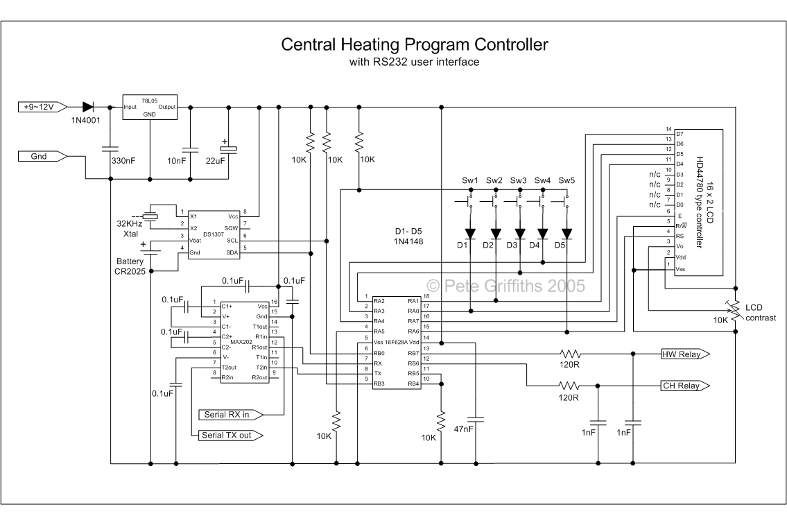
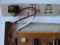
Hardware The
hardware for the programmer comprises two units. The first contains the
two relays
that switch the mains power to control the boiler. This also has an RJ45 socket
to allow connection into a CAT5 cabling system that takes power, serial data
and relay control input signals to the second unit, an intelligent programmer. There is also a 2.1mm DC power socket that is used to
connect an external 9~12V DC power adapter. This supplies power to the
relay board and the programmer controller. A 9-pin 'D' socket
provides connectivity to a PC serial interface. 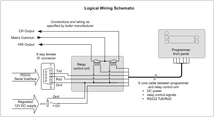
The
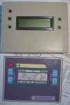
programmer unit is based on a PIC16F628A micro controller. The programmer
front panel has a 2x16 line LCD display that shows the time
and programmer status, with switches for manually overriding the
programmer. A serial interface for connection to a computer running a
terminal emulator allows complete control and programming of the unit
remotely. A Dallas DS1307 Real Time Clock (RTC) is used for time keeping and storing the program time
settings in its NVRAM. When power to the programmer is removed, the
RTC uses a 3V lithium coin cell to maintain the time, date and NVRAM data.
The
programmer control unit itself only draws about 10~15mA from the power supply. The current for the relays is
additional to this and the LCD used in the programmer is not
back-lit. The relays I used operate from 12V and draw ~30mA when
on. The 12V power supply for the whole setup as described only needs
to provide about 100mA. In practice something capable of supplying 500mA
would be better. The exact specification of the relays and LCD panel
used should also to taken into consideration when specifying the PSU. The
78L05 regulator IC shown on the schematic is not capable of
supplying power to an LCD panel with LED backlight.
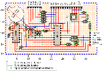
The
schematic diagram of the programmer is shown below, click on the image for
large copy. Construction details can be
found in the next section.
|
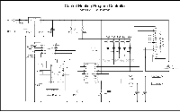
Programmer schematic (click to enlarge)
Schematic in PDF format
|
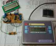
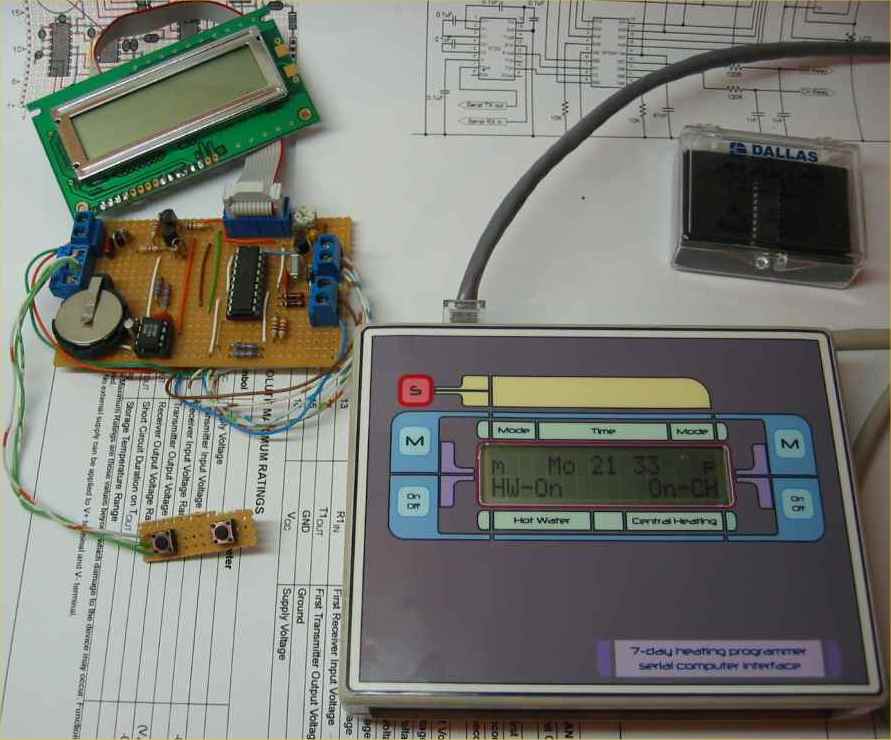
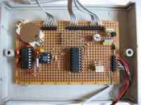
Final assembled
version and a development prototype. |
During development I used
the serial interface driver shown here
rather than the MAX202CPE device. This circuit is very cheap to
construct and works quite reliably from a PC. However, it does derive its
negative 12 volt supply in a parasitic fashion from the serial transmit
line of the host device. Therefore the host must drive its TxData line
with RS232 signal levels. If you don't want the expense of the specialized
driver chip and know what you want to connect to, this makes a cheap
alternative. To make
the final circuit more compliant and function reliably with any serial
device I made a decision to use the MAX202CPE line driver. A number of
manufacturers produce similar pin-compatible devices to the Maxim part
that could be used here.
I'm using the
programmer with the relays located at the end of about 10M
of CAT5 UTP cable. Although the PIC is driving the line, internal
protection diodes on the port pin will pass any spikes onto the power
rail. The 120 ohm resistor / 1nF capacitor on each
relay control output are there to slow rise and fall times on the output
and also filter any transient noise on the line from reaching the output
pins
of the PIC. The
display is a standard 2 x 16 LCD and the code is written for the HD44780
controller command set. The
relay outputs from the programmer were designed to connect to a logic level
relay interface and will not drive relays directly. I
used a 2-channel relay board kit from Quasar Electronics. Kit
No 3156. (This is made by
DIY
Electronics, their kit K156
which is resold by various
other
companies)
As I'm using the
programmer with the relay kit above I can say that the two work reliably
together. In principal there is no reason why you can't construct
your own relay driver. The one
shown in this schematic should
also work with 12volt relay coils.
The BC548 transistor shown can be replaced with any general purpose NPN
transistor. You will need to take into account the current drawn by
the relays and ensure that;
-
The transistor is
capable of sinking the current drawn by the relay coil.
Small PCB mount relays with a 12V coil will typically draw about 35mA
and the BC548 can sink 100mA continuous max.
-
If you use 5volt relays
remember that the 78L05 voltage regulator can only supply 100mA
maximum and that both relays may be energized at the same time. You
will therefore almost certainly need to use a 7805 1Amp regulator in place of the 78L05.
-
The relays used will need to
be specified according to the specific boiler being controlled, but
typically, for use in the UK a relay rated for 240V mains operation and 3A
contacts would be suitable.
-
If you locate the relays
remotely from the programmer as described here, you must locate the
relay driver circuit with the relays. Don't put the relay
driver on the programmer circuit board and then switch the current to
the relay coils through several metres of cable.
** This project involves
the control of mains voltages. If you are not confident about
working with high voltages or don't understand about wiring this into your
existing heating system you should employ the services of a qualified
electrician. You should also ensure you comply with any local
regulations with respect to the installation of the programmer **
Datasheets
Construction
The
following description of the construction is based on the unit I've built
myself which includes the front panel display and controls. The programmer
doesn't actually need the front panel interface. The software will
function correctly with or without the front panel interface components
installed,
so if you want to control it from the serial interface only, you can omit
the LCD display and 10K contrast preset, switches Sw1 thru Sw5 and diodes
D1 thru D5. You must keep the 10K pull-up resistor to pin 4 (RA4) of the
PIC. You could also use it with the LCD display but without
the switches.
| The
main programmer unit is housed in a 130 x 95 x 30mm ABS case. (See
Rapid Electronics part # 30-3892 by Evatron) The LCD
display panel and five push button switches are mounted in the top half of
the case. When mounting the switches the top of the buttons should
be just proud of the top of the case, this makes them
easier to operate once the front panel overlay is fitted. The
switches have then been fixed using hot-melt glue.
The ribbon cable to the LCD panel was fitted and then LCD glued into the
case, again using hot-melt glue. Once all the
cables to the top of the case were fitted some hot-melt glue was used to secure them and
provide strain relief . The use of hot-glue does make
it difficult to replace or repair parts in the future but not impossible.
Since it's a one off project I was happy with the ease of construction and
felt this outweighed maintainability.
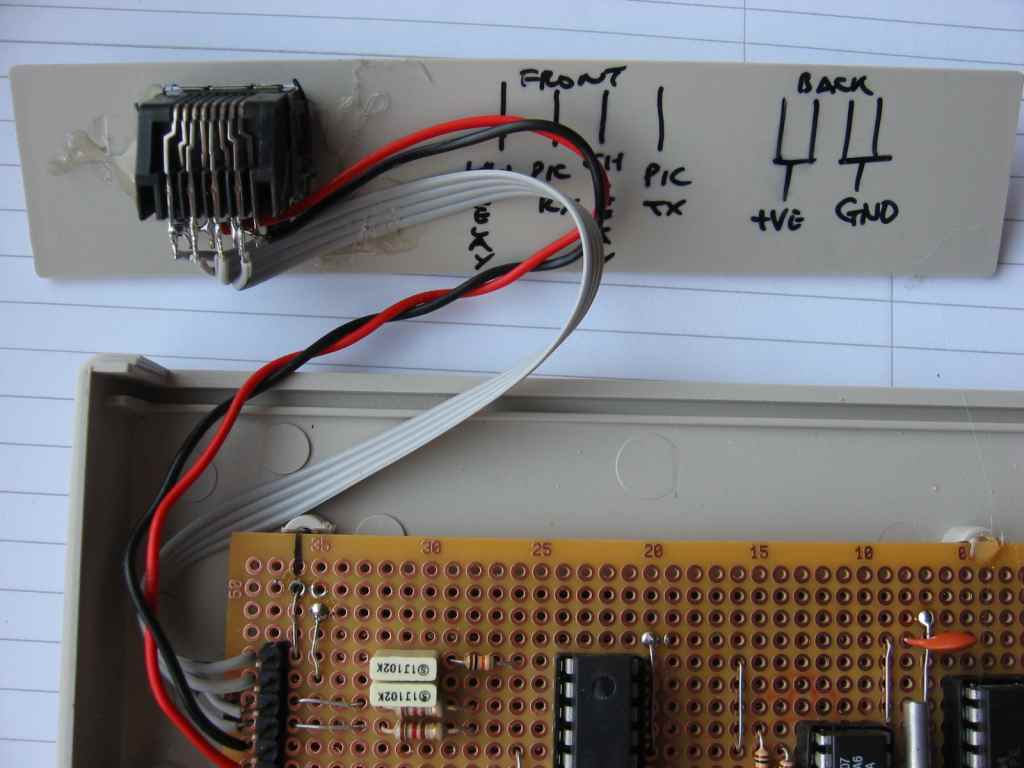
An
RJ45 socket was removed from a Network Interface Card and used for
the external connections. A
cut out was carefully made in one of the end panels. This was then
attached using hot-melt glue and the cabling attached afterwards.
Keeping the cut-out an interference fit with the RJ45 socket helps keep it
nice and solid when assembled. |
|
The
main control board was fitted in the bottom half of the case and secured
with a couple of small dabs of hot melt glue. The moulded mounting pillars in the bottom of the case where shaped to hold the
board mechanically so only the smallest amounts of glue where needed to
secure it. This was done intentionally so that it will be easy to remove
the board.
| The central heating boiler
in my home is located in the garage next to the data comms'
cabinet. There's a standard commercial heating programmer that was
installed with the
heating system and I have wired my control box in parallel with
this. When my programmer is operating, the commercial programmer
is set to manual off. This means I can easily revert back to
using the commercial programmer if needed.
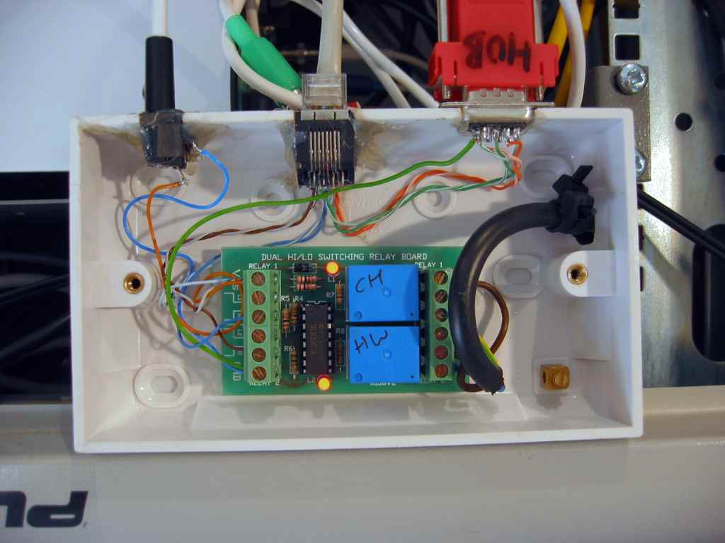
A 40mm deep double gang surface mount box has been used to
mount the relay control board and connectors. Slots have been cut
into one side of the box to take a 2.1mm DC power socket, RJ45 socket and
9-pin 'D' connector. The three wires from the boiler are brought in through a hole in one end of the box and secured with cable
ties. The relay control box is located in the bottom of the comms'
cabinet which allows it to hook up to the PC (also located in the
cabinet), the CAT5 cabling patch panel and power from a small 12volt
/ 500mA plug-top adapter.
I have a small PC in the bottom of
the cabinet that functions as a file server and systems controller
for the house, so this was the logical system to connect the serial
interface to. A terminal emulator runs on the PC and this is
accessed via a remote desktop application.
|
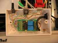
Relay control box with the cover removed.
|
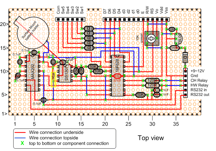
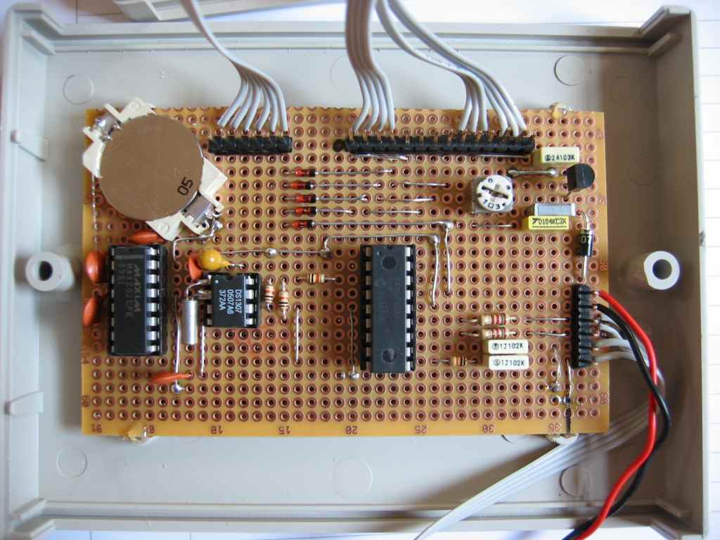
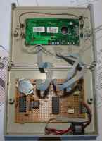
The main programmer has been constructed on double sided matrix board and a
detailed construction layout is provided below. Construction is
fairly straightforward and should be done in conjunction with the
schematic diagram provided in the hardware section above.

Circuit
construction notes:
-
The 10Kohm resistors are
1/8 watt devices and somewhat smaller than standard 1/4 watt carbon
film types. You can use 1/4 watt resistor but you will need to mount
them vertically if you follow this layout.
-
The 47nF capacitor
shown on the schematic diagram decoupling the power rail to the
16F628A has been soldered on the reverse side of
the board directly across the Vss-Vdd pins of the PIC. See
Photo
-
The oscillator pins of
the DS1307 RTC device have been bent out horizontally from the
package, the narrow ends of the pins cut off and the crystal soldered
directly to the stubs on the IC. I've done it this way because it's
difficult to meet the layout requirements for the crystal circuit as
detailed in the datasheet for the device without using a PCB.
Done the way I've shown the RTC clock should run very
accurately.
-
The battery holder used
was a surface mount type, tacked to the copper pads on the top side of
the board. After
construction visually inspect the connection between the +VE terminal of
the battery holder and pin 3 of the DS1307 socket to ensure there are no shorts to ground or anything
else.
-
Once
the board has been assembled, apply power to the board before
inserting the three IC's or connecting the LCD. Ensure that 5volts appears at the IC sockets
power pin positions and the LCD header. Correct any problems.
-
Adjust
the LCD contrast preset so pin 3 of the LCD header plug is at 0v.
-
After
the power supply has been tested install the three IC's and connect
the serial interface to a PC running a terminal emulator
application. The programmer will function for testing purposes
without the LCD or switches connected so you can check the basic
functions through the serial CLI interface and then connect the LCD
and switches once you've established the basic operation of the
circuit is okay.
-
With
the LCD connected, adjust the contrast preset resistor until the
display can be read.
-
Switch functions
Sw1 - HW on/off
Sw2 - CH on/off
Sw3 - HW manual
Sw4 - CH manual
Sw5 - 'Setup' button
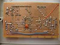
pad board construction layout
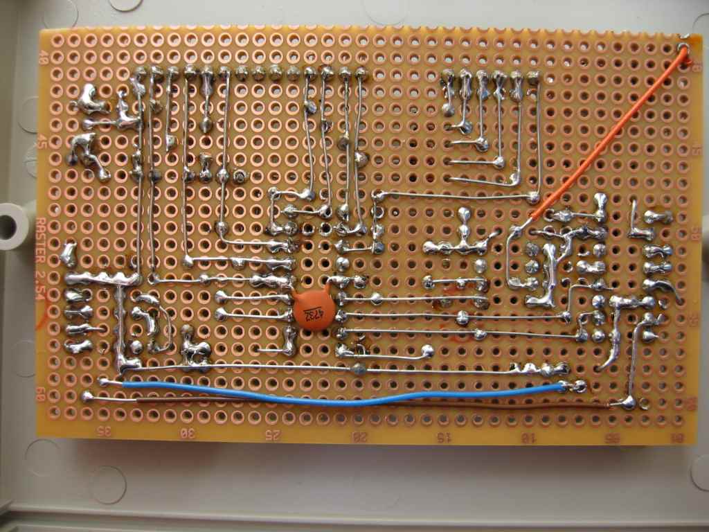
|
Assembled board
|
Reverse side of board
|
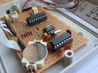
Detail of battery holder
and 32Khz crystal |
Assembled programmer
|
RJ45 socket detail
|
Although I installed
connector pins for attaching the LCD display, keypad and RJ45 socket, I
ended up soldering the connecting cables directly to the board, mainly
because I didn't have the necessary sockets and also because once
assembled it isn't likely to be opened up again.
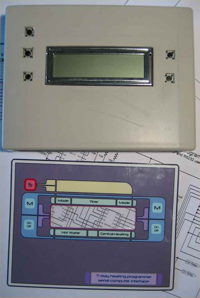
Front panel artwork
| Artwork for the front
panel was produced using Microsoft Visio. This was then
printed onto photo quality glossy paper. Once the ink was dry (make
sure it is or you'll be doing it again) the area where the LCD
panel locates was carefully removed and the whole artwork cut out
from the A4 sheet.
This was then laminated using a
normal office document laminator. The only thing I did before
laminating was to work out where the switches would be and then cut
out rectangles in the second layer of the laminating sheet.
This reduces the stiffness of the completed panel and makes the
operation of the switches underneath more tactile. |
|
Once this was done I used some
fine sandpaper to rough up the surface of the case and the back of the laminated
artwork. DO NOT sandpaper the LCD screen or the window in the laminate
sheet, in other words do it carefully. Once the surfaces were prepared and
cleaned off, the laminate was stuck to the case using a cyanoacrylate glue (Superglue)
Operation
When
the programmer powers-up it displays the firmware version on the LCD
display for 2 seconds. It then checks two validation bytes in
the RTC NVRAM. If these do not contain the correct validation data the
LCD will display RTC Initialized for 7 seconds, other wise it displays RTC
ok for 2 seconds.
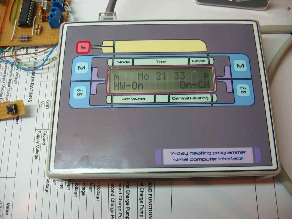
In normal operation, the LCD display shows
the status of the CH
and HW outputs, manual mode status and the day and time. A separator
':' between the hours and minutes on the display blinks every
second.
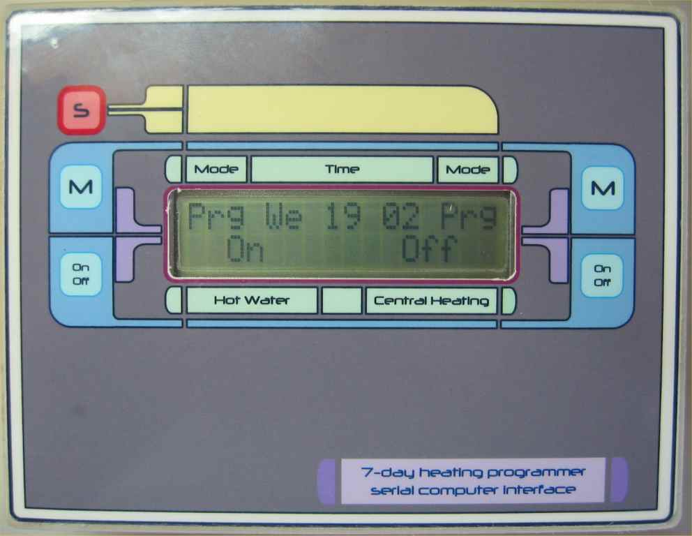
Photo right: Programmer
with FW Rev 1.8
Photo far right: Programmer with FW Rev 1.9
|
|
The front panel of the programmer
can be used to turn the Central Heating (CH) and Hot Water (HW) boiler controls
on or off independently using the buttons located either side of the LCD
panel. The status of each output is displayed on the LCD.
There are also two buttons to
toggle the CH and HW operation between program controlled and manual. In
manual mode, program settings are ignored. The manual mode status is shown on
the top row of the LCD with 'Man' for manual and 'Prg' for program. When operating in
manual mode the heating and hot water can still be turned on and off using the front panel or from
the serial interface.
If the LCD displays the word
'Locked' on line 2, then the front panel switches have been disabled from the
serial CLI. The unit can still be controlled from the CLI and the LCD continues
to display time and status. The front panel can only be re-enabled from
the CLI.
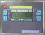
For details of operating the programmer, follow the links below
Front
Panel Setup Operation
CLI
operation
Disclaimer
|