I'm a big fan of the Terminator
film series and earlier this year I came across a T800 resin
model in a shop and decided it would look good in my workshop.
These models are readily available from lots of sellers on eBay
and elsewhere.
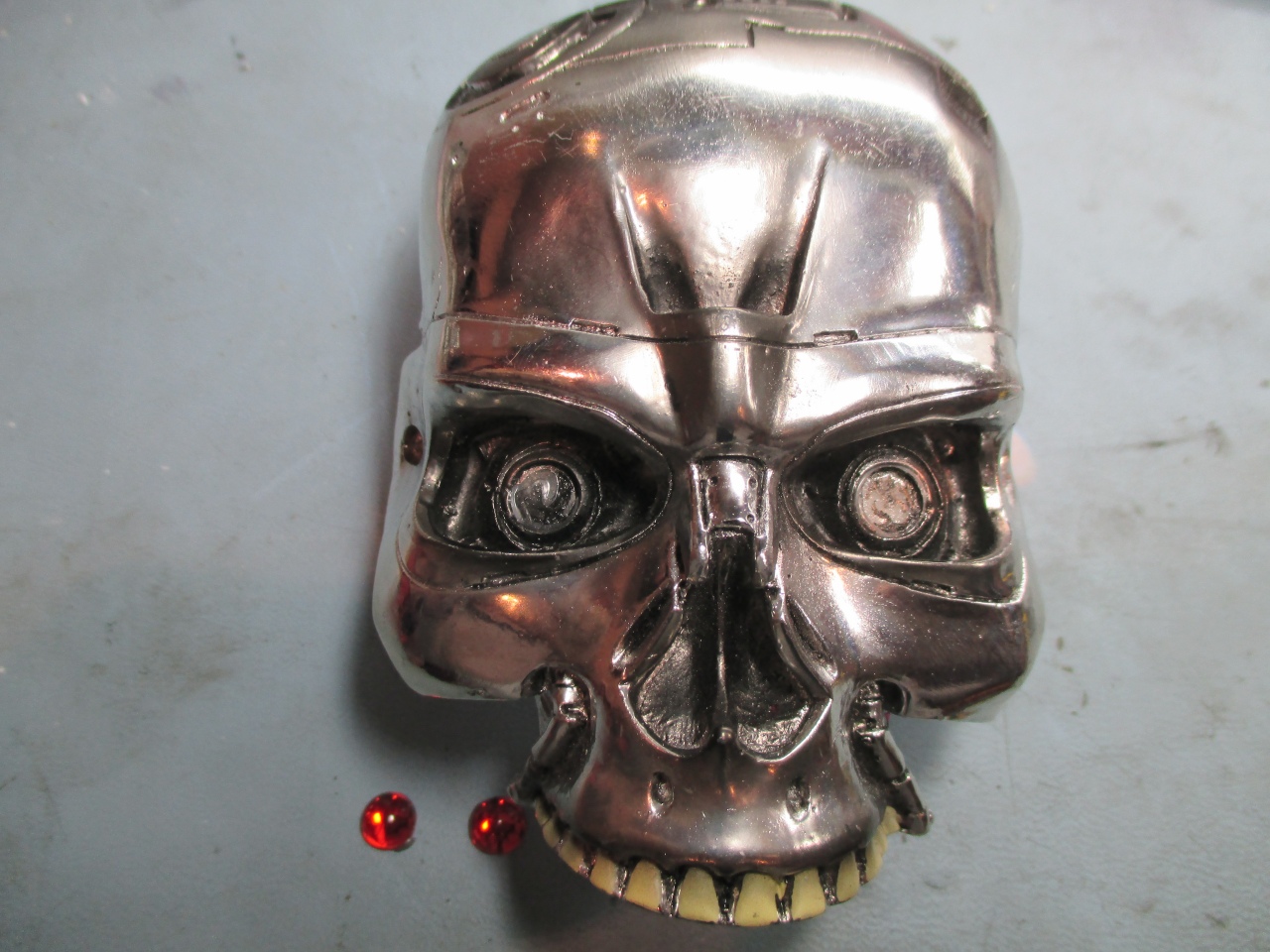
So it looked pretty cool but the
eyes let it down, it just looked like a dead Terminator. I
did a bit of investigating and found the red eyes on the model
were easy to remove, further investigation saw a couple of 5mm
holes drilled through the eyes of the skull and a two red LEDs
fitted - it looked really good but I thought it would look
better if those LED eyes could be animated. I have a previous
project that uses 3 channel PWM to control RGB LEDs so I took
that and used two channels and some new sequence data to animate
the Terminators LED eyes.
Follow the rest of this web page
to see how it was done, and if you like it, there's a
kit available
with the electronic bits so you can make one yourself.
It uses a
microcontroller with software based on
the RGB Mood Light project and some custom sequences to
animate the LEDs so they don't just glow red but can
fade and flash independently. The whole
circuit operates from 3 volts using a couple of AAA
batteries which will run for many hours.
A single push button
switch is used to control it.
Power
When off, Press for 2 seconds and release to
bring it out of standby
When on, Press for 2 seconds and release to go
into low power standby
Effects
A single short press
will
freeze / run the effect.
A double press (think
double clicking a mouse) to switch to the next effect.
There are 6 effects and 3 markers so you can keep track
of where you are as you double-click through the
effects.
Effect #1
Marker: Slow blink
right eye (as you look at it)
Effect #2
Effect #3
Effect #4
Marker: Slow blink
left eye (as you look at it)
Effect #5
Effect #6
Marker: Slow blink
left+right eyes
...returns to
Effect #1
At 10 seconds after the
last switch press, the current effect/mode is saved to
NVRAM so it always powers up using the last saved
effect, even if the power/batteries are removed.
Since this is based on the
RGB101 Mood Light project (see
here for details) I'm not going to go into depth on the
details of the circuit and operation.
The circuit used here is a cut
down version of the RGB101 project. Since we only need two
Red LEDs and it operates from a 3 volt supply the original
voltage regulator, driver transistors and multiple LEDs are not
used. The firmware is the same but the sequence data has
been customised to generate suitable effects for the Terminators
two eyes.
Power Supply
The project requires 3 to 4.5
volts to operate and as shown here it runs from two AAA
batteries at a nominal 3 volts. The power consumption is
minimal and the circuit will run for many hours on a set of
batteries.
If you wanted to run it from an
external power supply, the PCB has the option to operate from
9-12 volt supply if a 5 volt regulator is used on the board.
(See original RGB101 project for schematic)
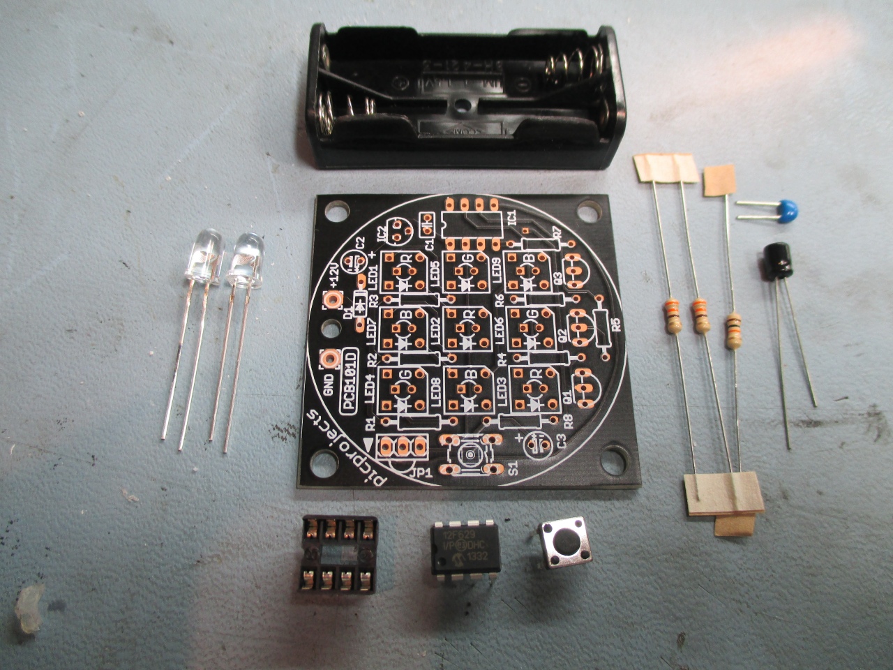
It's not too difficult to put
this board together but a soldering iron suitable for electronic
assembly and previous experience of soldering is advised.
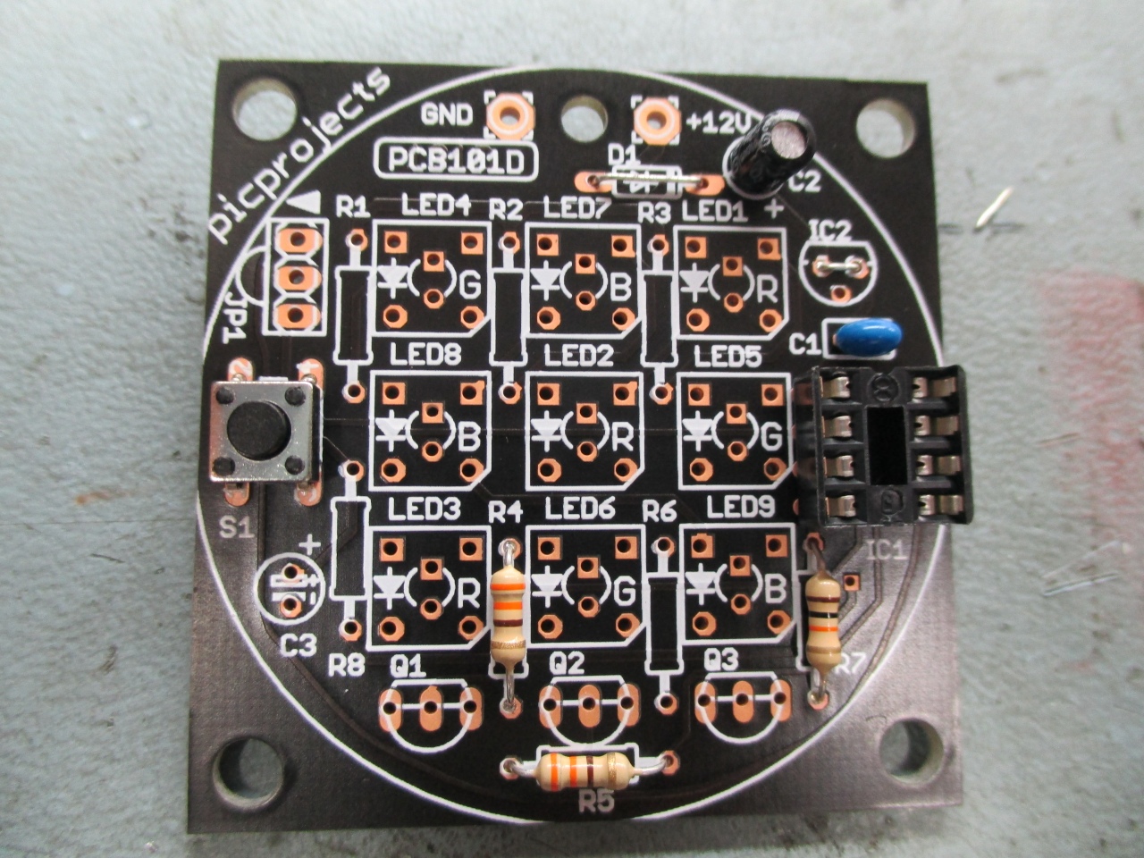
Fit the three resistors. These
have coloured bands on them and it is important they are
fitted in the correct positions.
R4 & R5:
orange-orange-brown-gold
R7:brown-black-orange-gold
Also fit the two wire
links (arrowed green in the photo) to positions D1 and
IC2. Use the excess lead cut from the resistors for
these links.
Fit IC socket, switch and
capacitors C1 and C2.
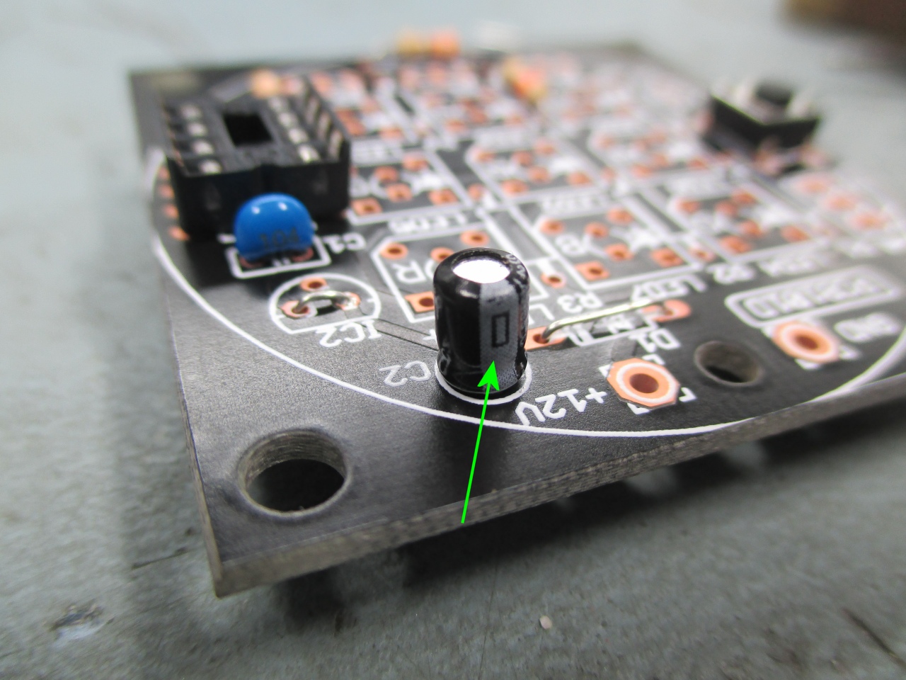
C2 must be fitted the
correct way round as shown in the next photo.
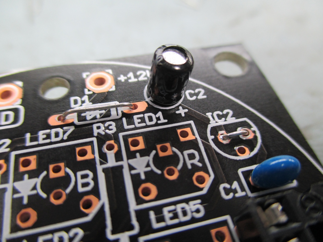
Capacitor C2 has a white
band down the side (arrowed green in photo). It
must be fitted so the white band is towards the outside
edge of the PCB as shown here
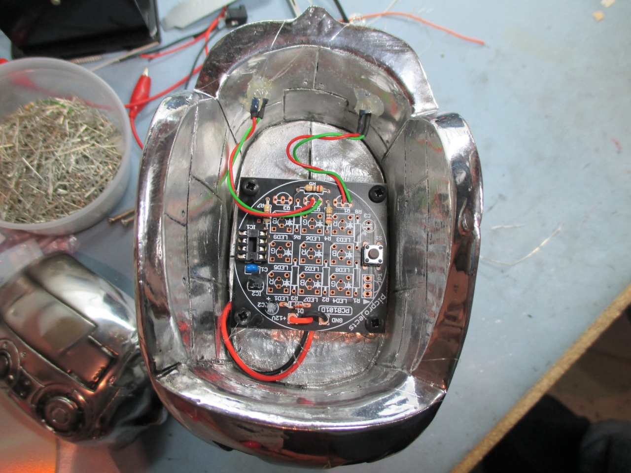
Note wire links fitted
to positions D1 and IC2. Since the actual
components aren't used in this application the wire
links are required to jump the electrical connections.
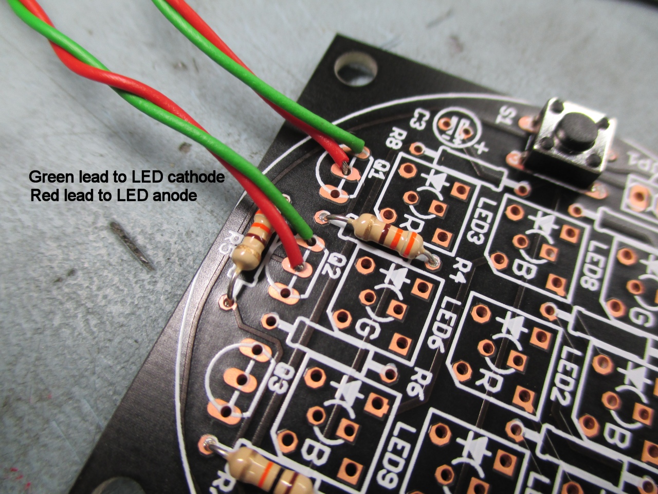
Solder fly leads to each
LED as shown. Note the flat on one side of the LED
plastic body. This denotes the cathode terminal.
Solder a green wire to the pin nearest the flat and the
red wire to the opposite pin
Solder the LED fly leads to
the main PCB as shown. It is important that the
LED anode and cathode terminals are connected the
correct way round. If they are connected the
opposite way round they won't light.
Pass the battery holder
leads through the centre hole and solder to the
positions show. (although it is marked 12 volts
you must not exceed 4.5volts since we are not using an
onboard voltage regulator)
Install the PIC
microcontroller into the socket. It has a dot and
notch in the plastic package at one end. You
must fit it with these towards capacitor C1 as
shown above.
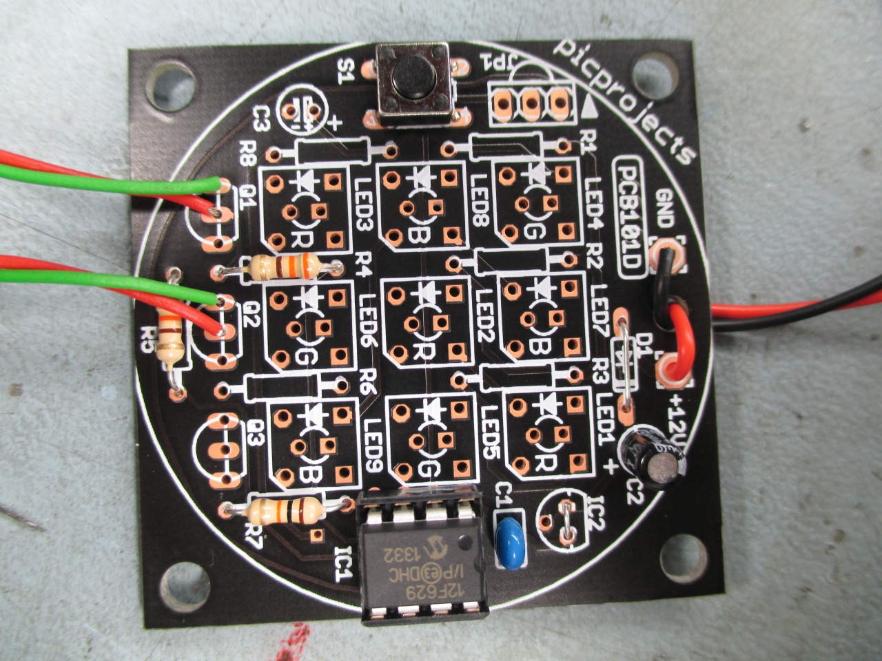
Overall view of the
completed PCB
Modifying the Terminator
model
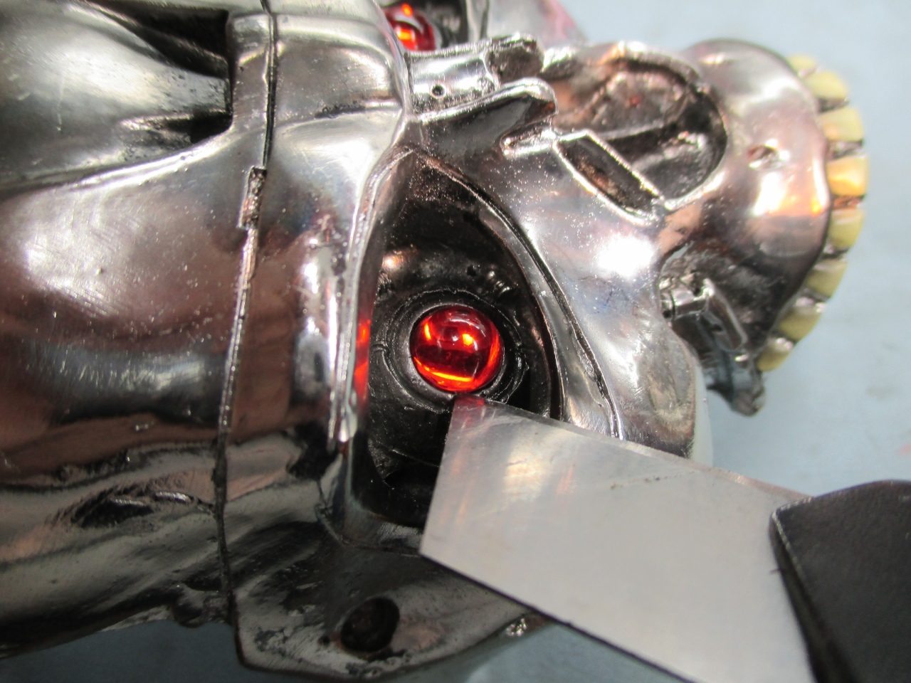
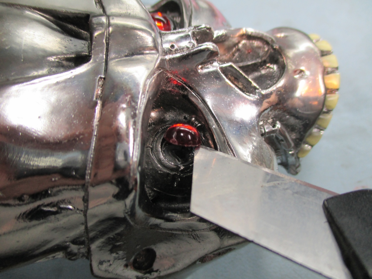
Carefully lever the eyes
away from the resin body use a flat blade
On all the ones I've done
so far, they have come away quite easily.
Both eyes removed and
ready for the head to be drilled
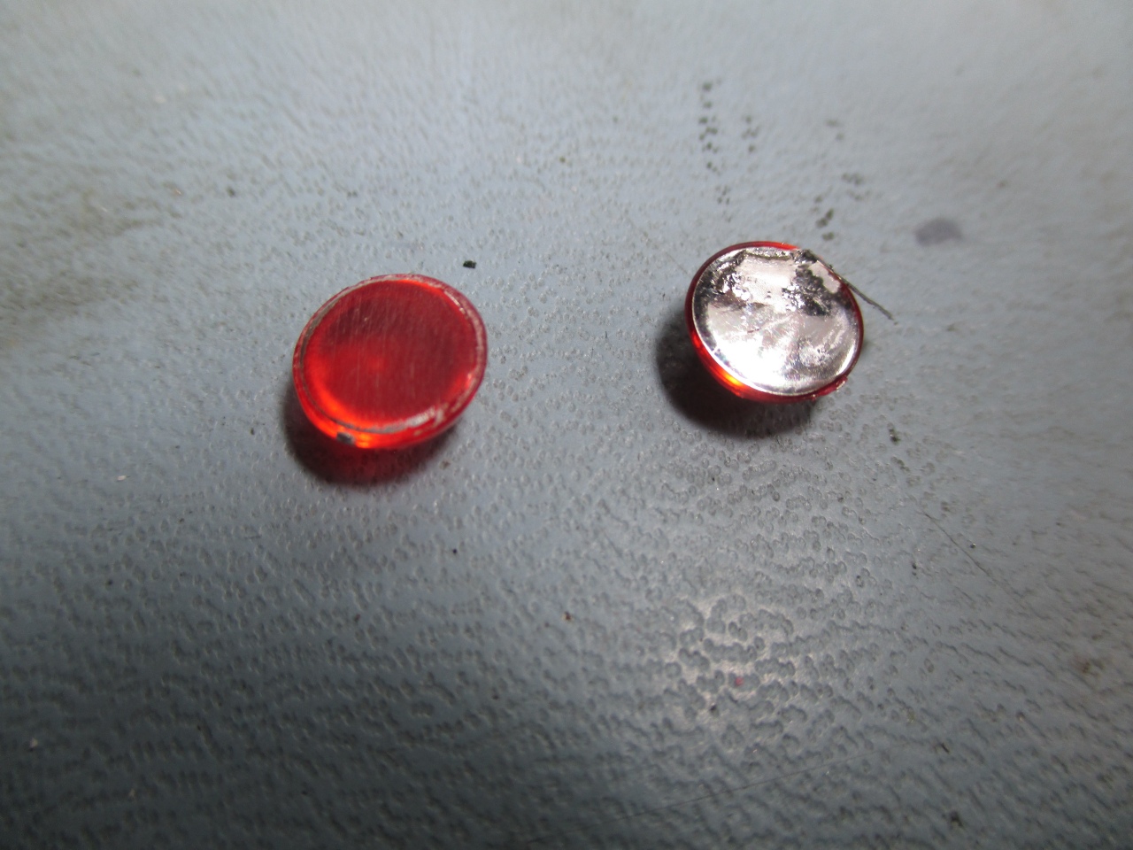
Take the eyes and use fine
sand paper to remove the silver paint from the back.
On two of the models I've
done the back of the eyes were slightly concave.
In this case you may
need to scrape the paint from the centre otherwise you
will sand away to much material.
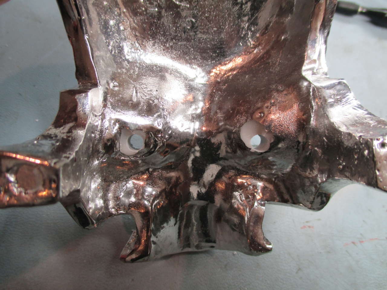
Drill a 5mm hole into the
centre of each eye. You may want to mark the
centre before drilling as I found it difficult to keep
it centred.
Drill from the front to
the back. You may find the resin blows out as the
drill comes through the other side and you wont want
this to happen on the front.
I used a Dremmel to remove
some additional material at the back to allow the LEDs
to seat fully in the holes.
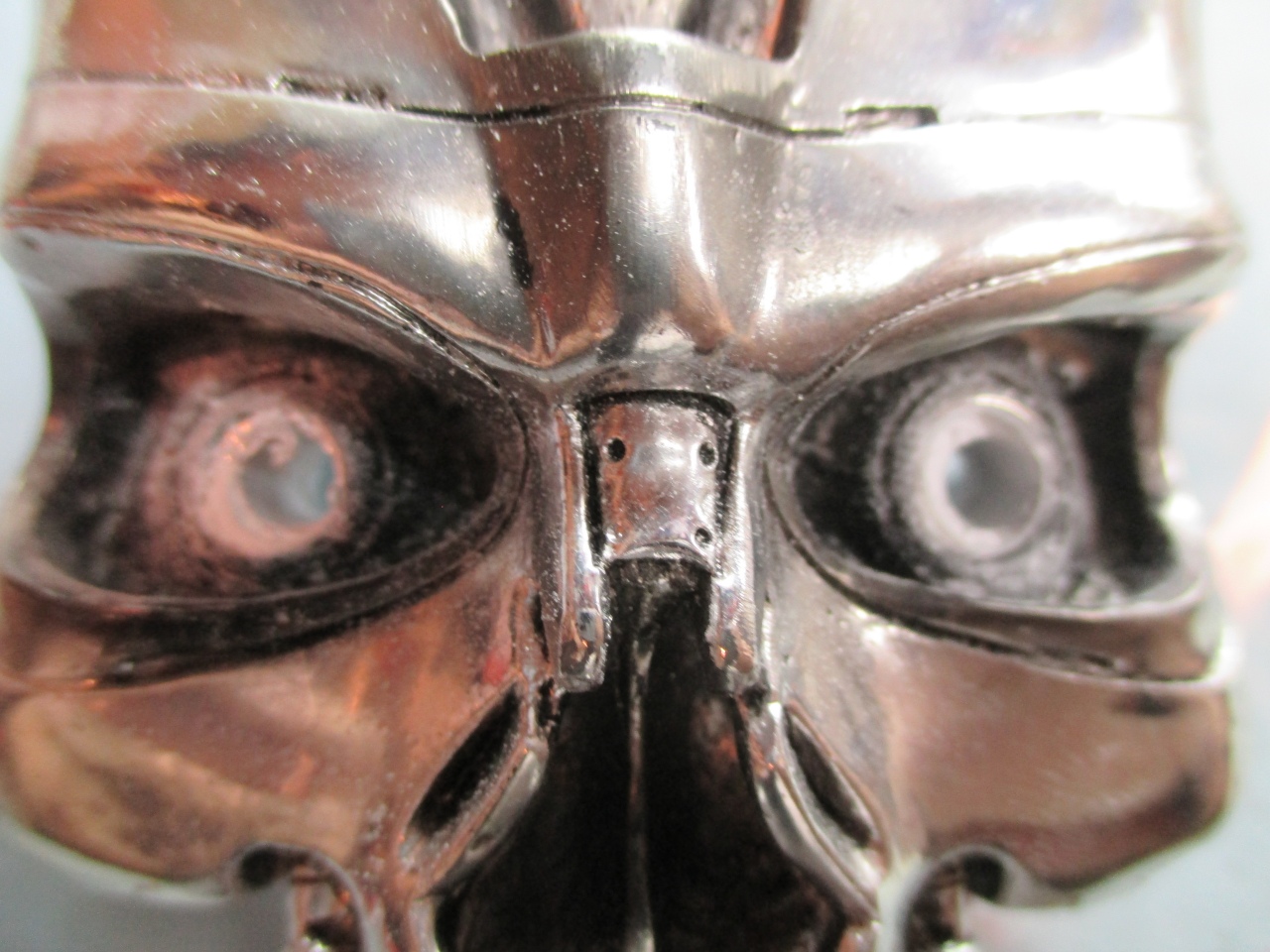
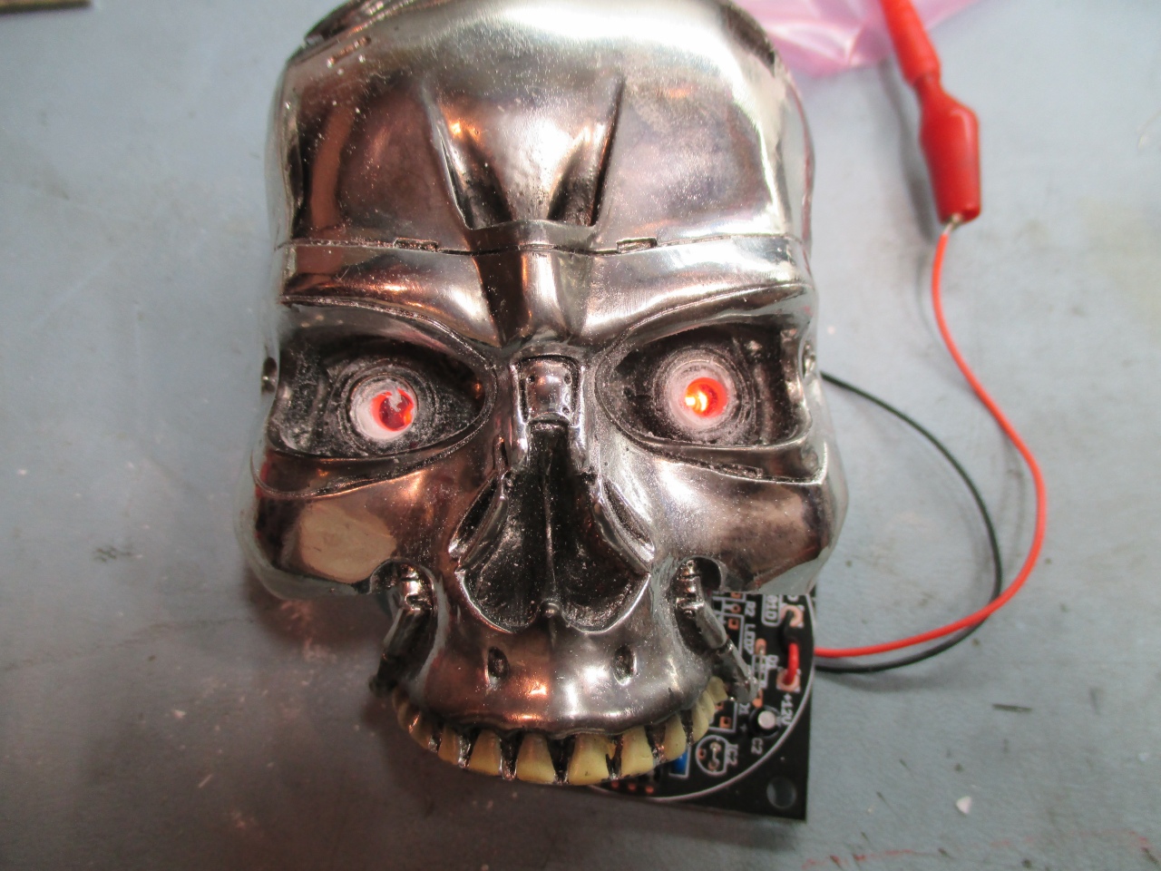
Quick test with the LEDs
installed before permanently gluing in place
Hot-melt glue is used to
fix the PCB and LEDs into the top of the skull.
I've done a couple of these and found the resin shape
inside varies quite a bit. On this one the PCB
seated okay but another one I did required some
material removing with the Dremmel to allow the four
corners of the PCB to seat better.
Glue the eyes back into
the front of the skull. You only want the glue on
the very outside edge, not all over the back. It's
a bit tricky to do this with hot-melt glue so you might
want to try some other adhesive or silicone sealant that
allows more time to apply and position the eyes before
setting.
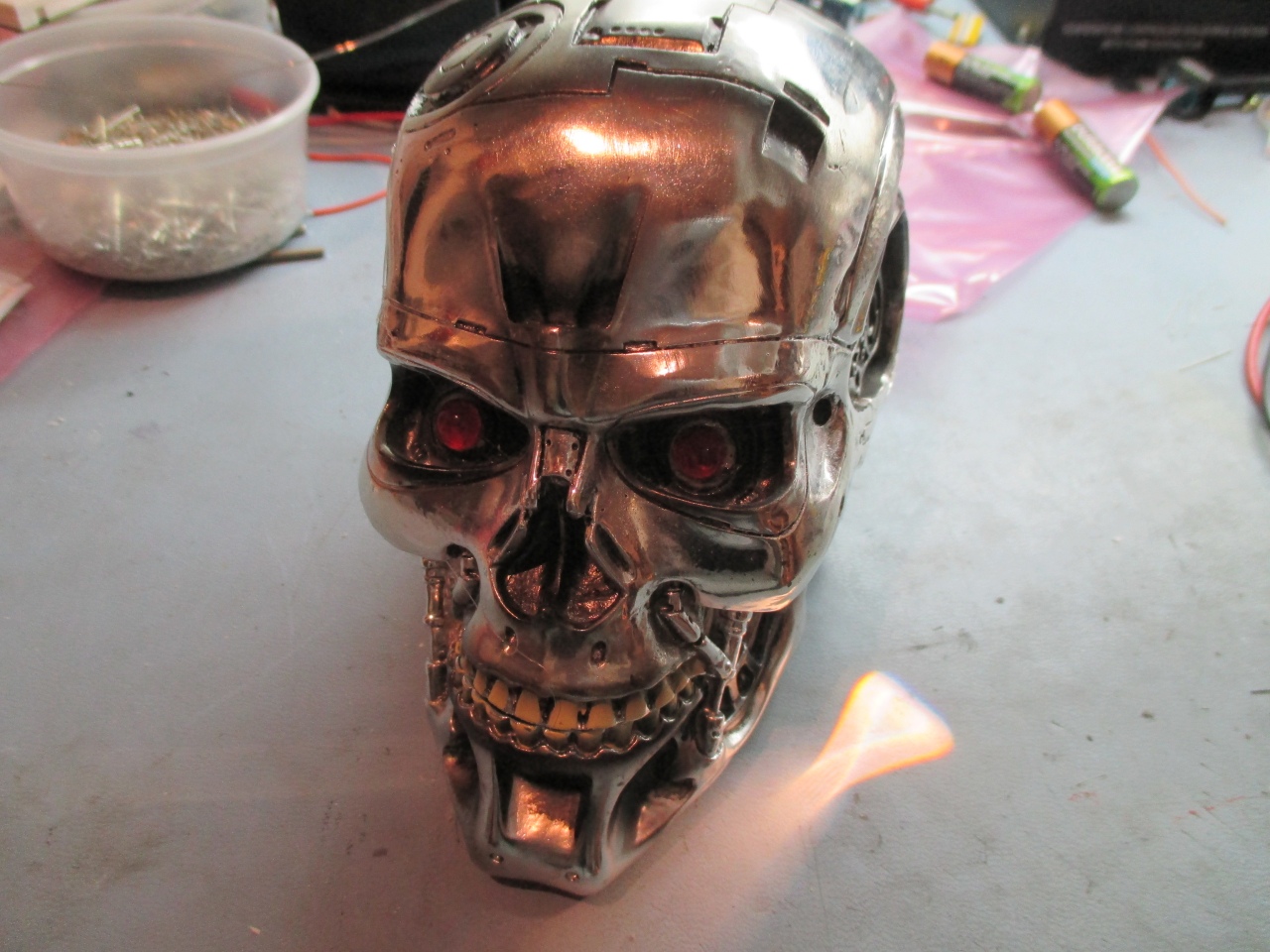
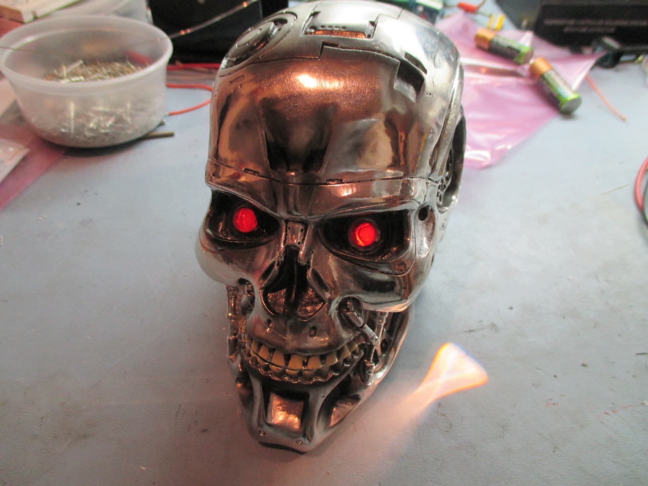
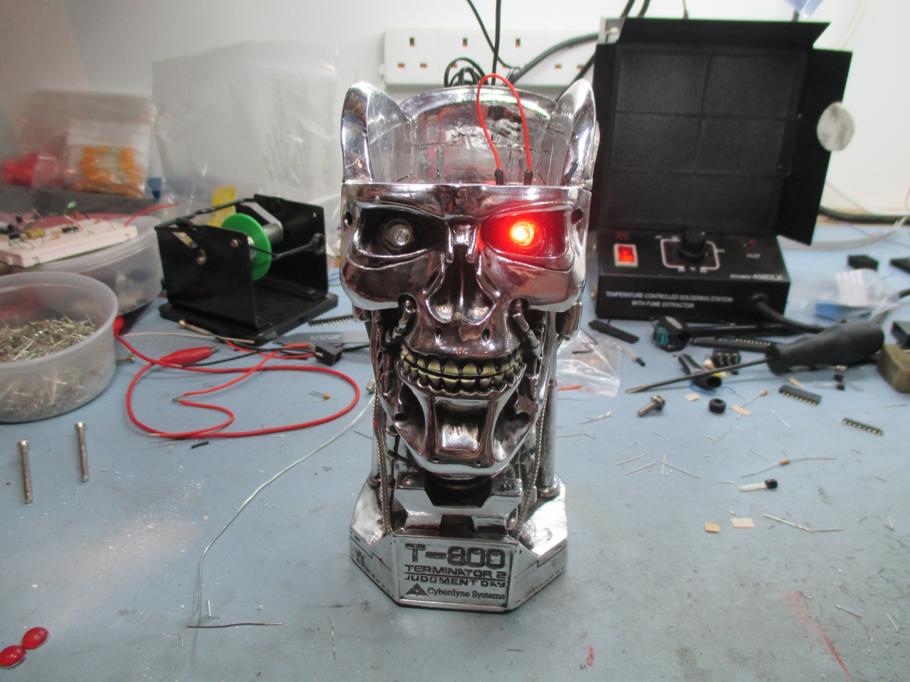
The modified T800 complete
and powered up.
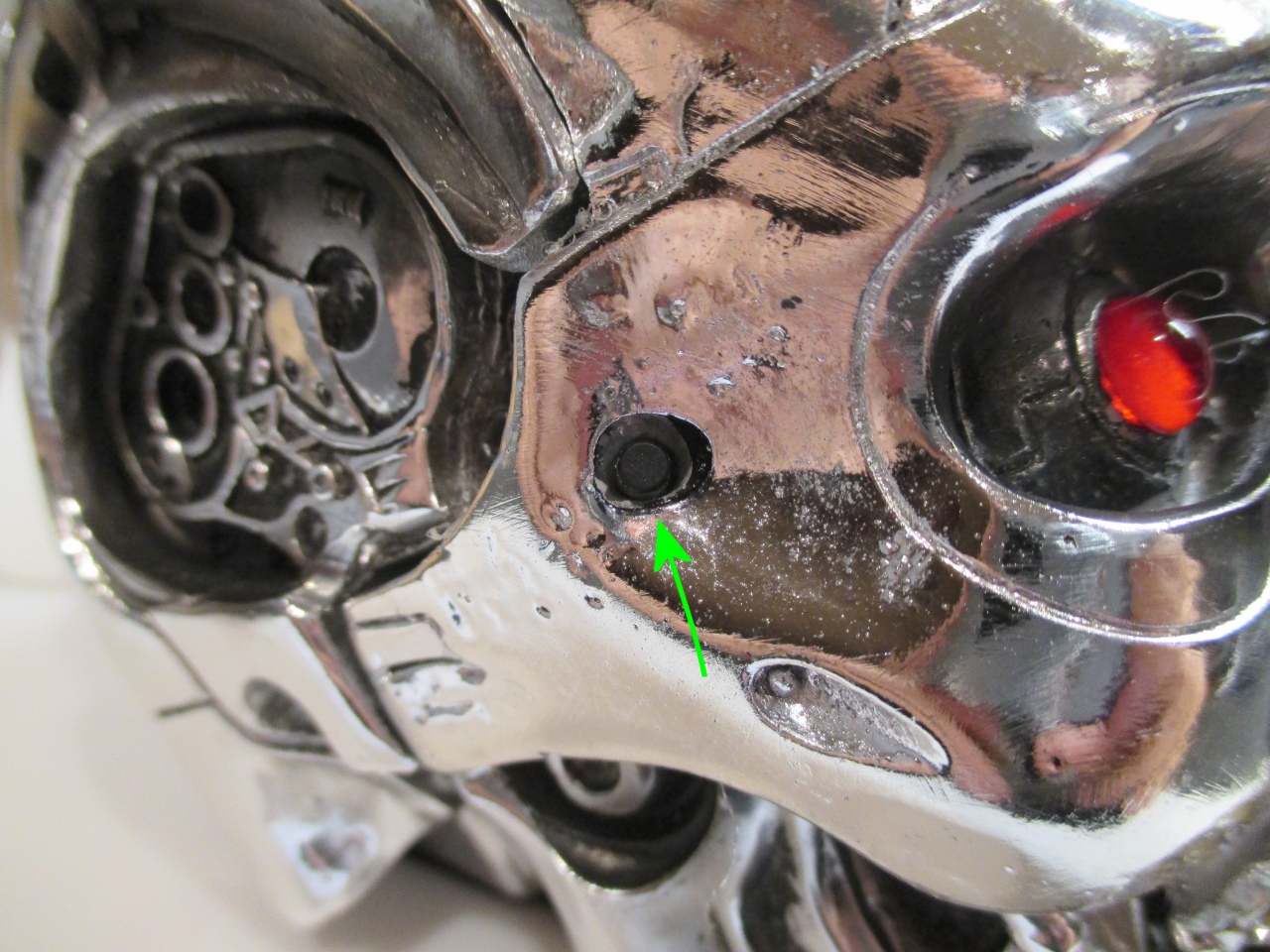
The modification in the
next two photos shows how a
switch was fitted into the side of the skull. It uses a
tactile switch with a 9mm long button. A hole was
drilled through the skull and the back of the skull
ground away with a Dremmel so the button just protrudes
through.
(this additional switch
is not supplied in the kit)
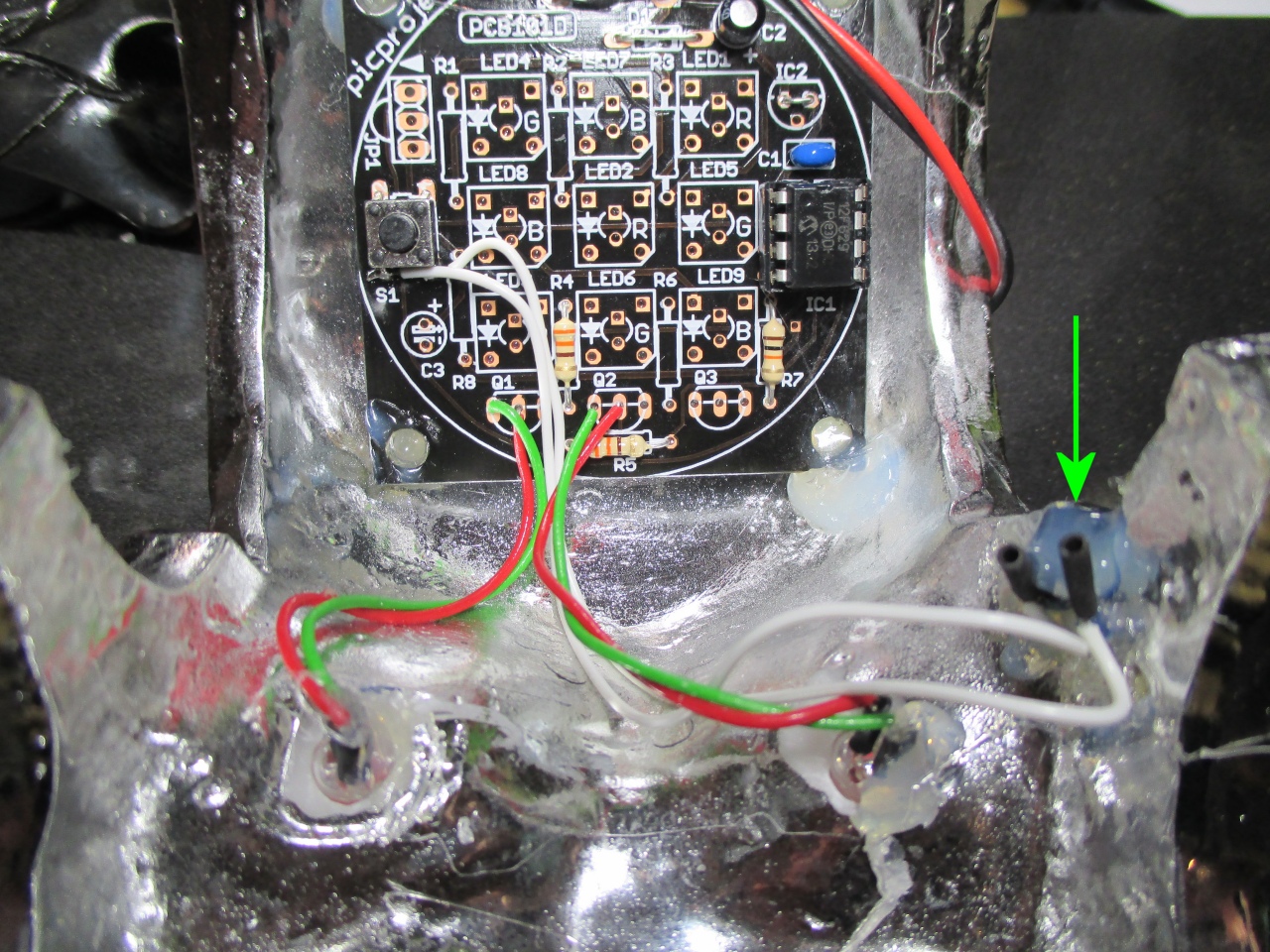
On the inside of the skull
the switch is hot-melt glued into place. Be
careful not to get glue under this switch and onto the
button itself.
It is
wired in parallel with the switch on the main PCB.
Either switch can then be used to control it.
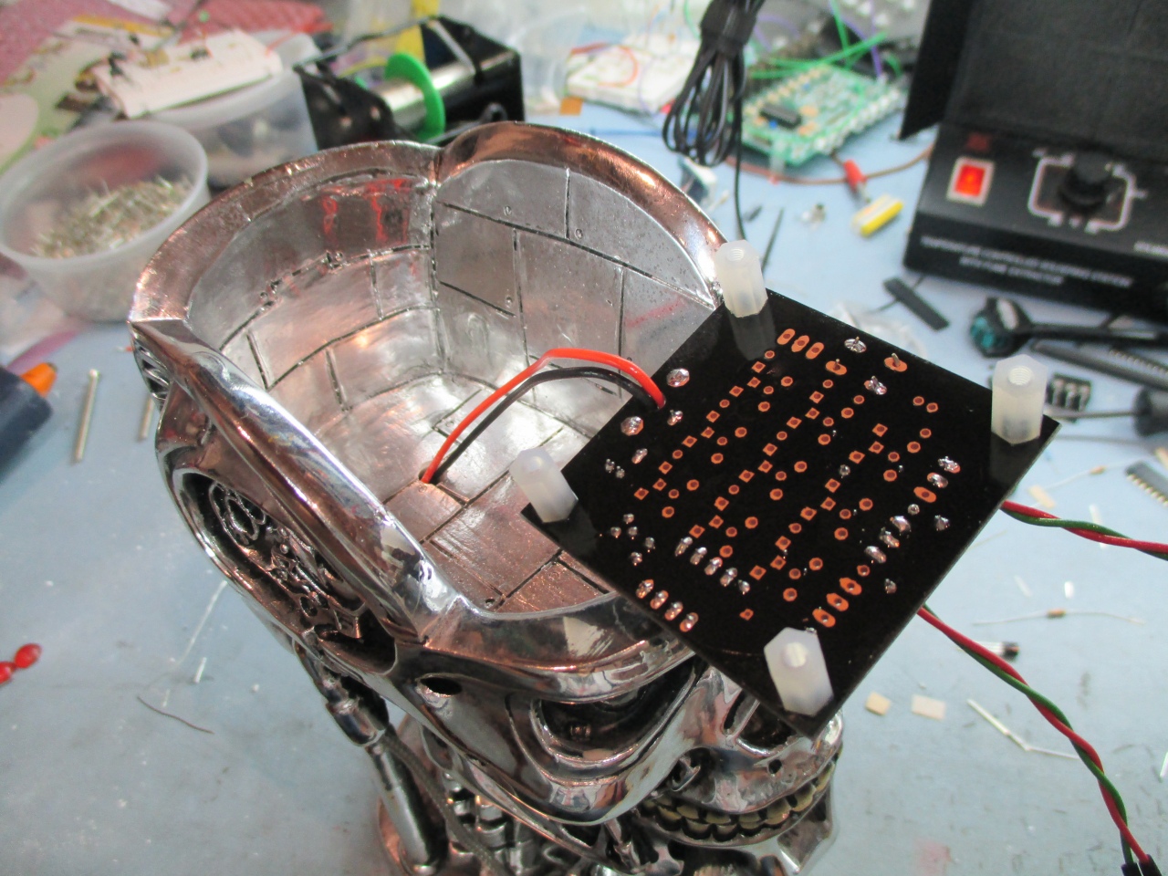
Photos below show the
larger T800 model. The head is physically the
same size as the one above but the top of the skull
lifts off rather than the whole top and face of the
other model.
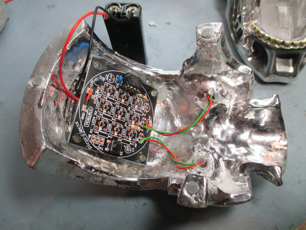
With this one I used an
external power supply connecting at the base of the
skull so there are a couple of extra components on the
PCB. I used four plastic PCB pillars to space the
PCB and hot-melt glued them to the inside of the skull.
This layout would work just as easily with a battery powered
version above.