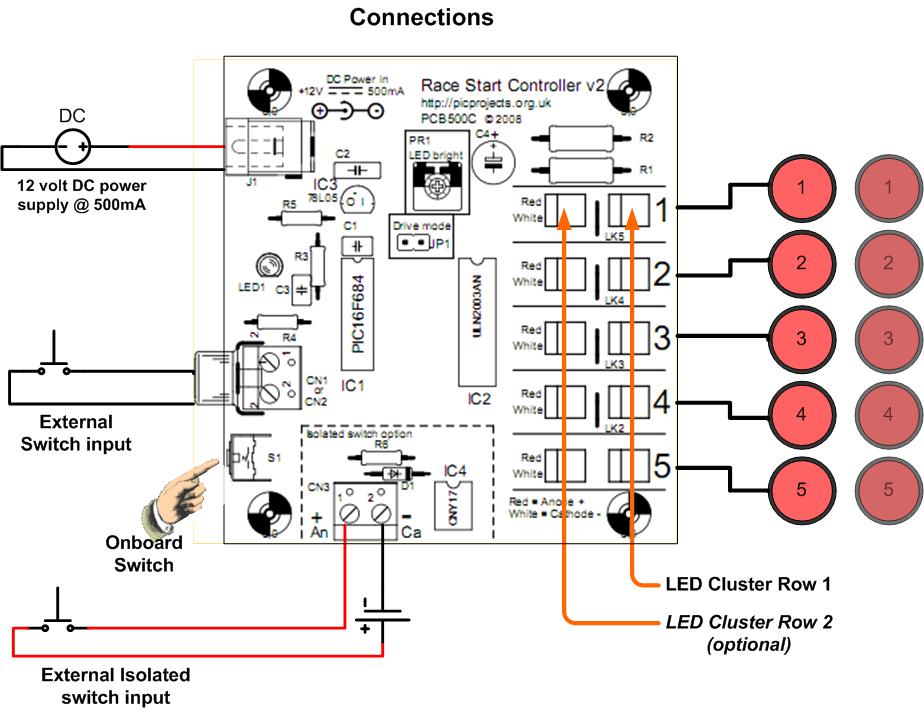
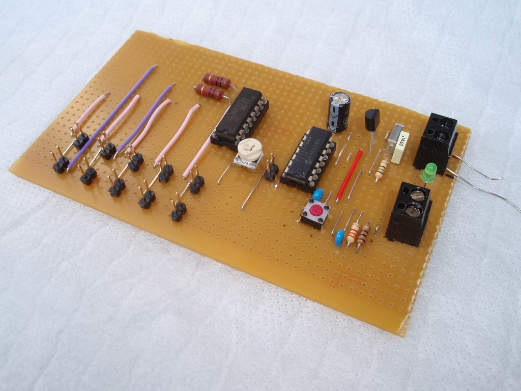
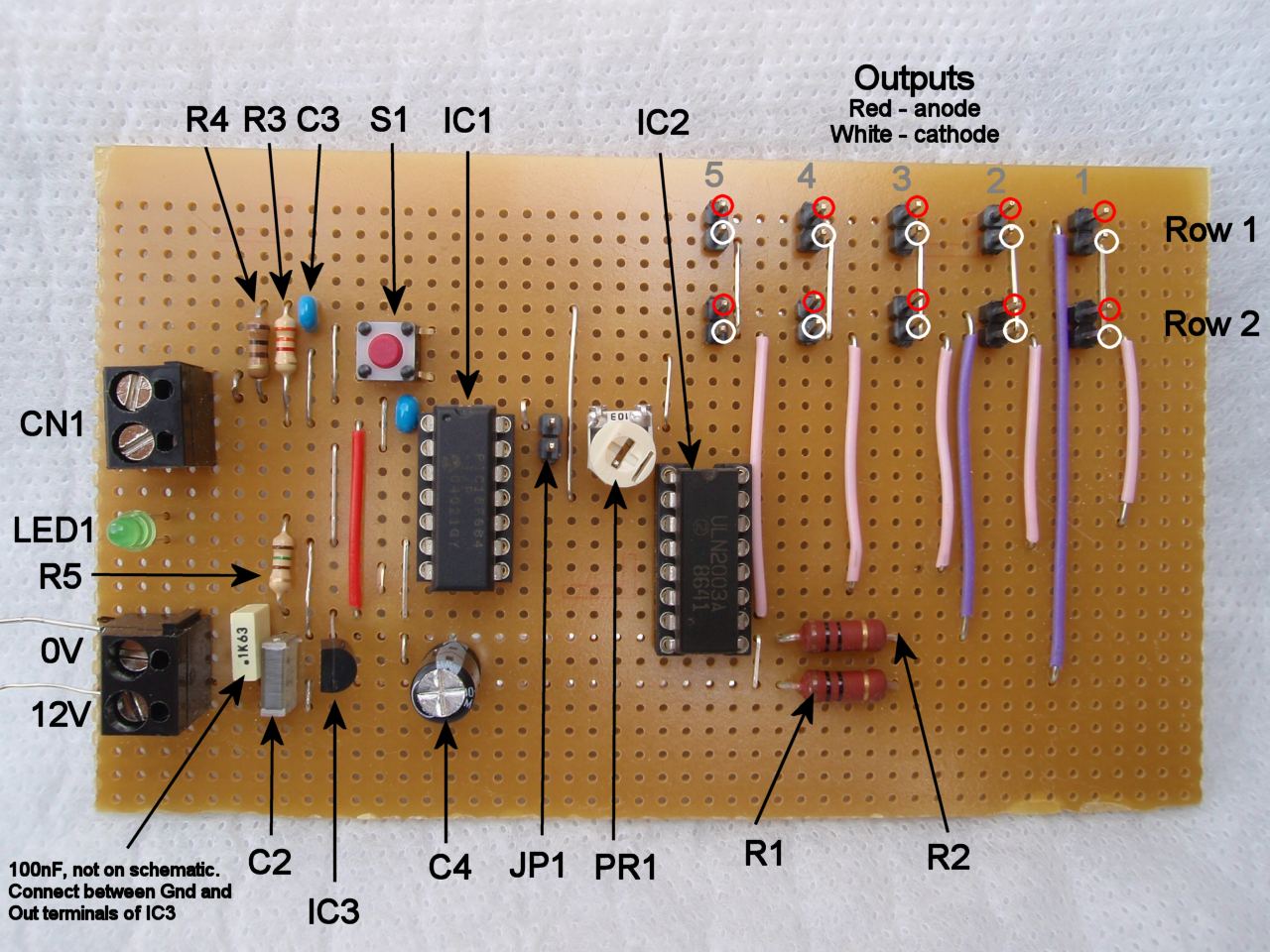
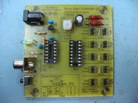
Construction details
for the PCB version are presented in pictures below. The PCB
can be built up to drive either LED clusters or off-board relays but
not both. There are a number of build options which
require a choice to be made as to which parts are installed and
these are described with the accompanying text.
A full component list
and part numbers for Rapid Electronics is provided at the end of the
section.
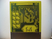
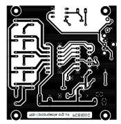
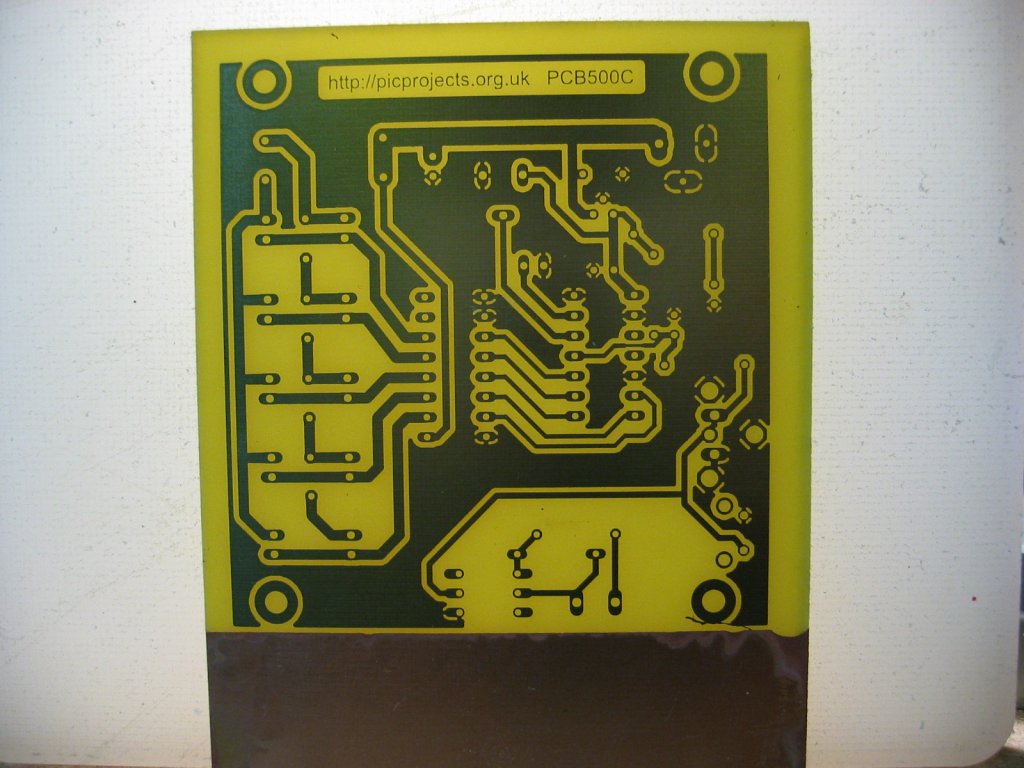
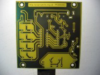
PCB straight from the etch
process |
PCB after drilling. Note the
three holes for the DC power connector (top right) need to
be milled into slots. |
Solder the small components to
the board first. Fit the voltage regulator (IC3) so it
matches the profile on the overlay. You may need to bend its
centre pin out slightly to line up with the holes in the
PCB. |

Next install the medium sized
parts. |
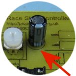
C4 needs to be installed with
the negative lead the correct way round.
|
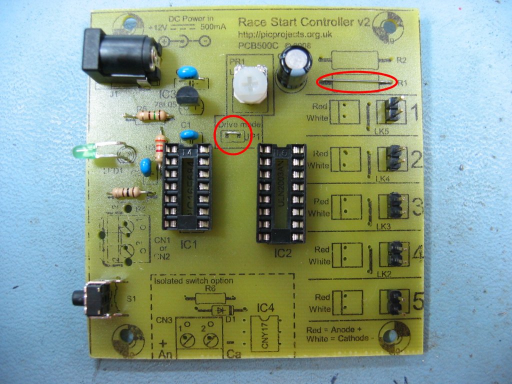
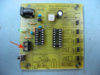
If you construct the circuit
to drive off-board relays,
install wire links into positions JP1 and R1 (circled red).
Do not fit R1 or R2 or the second row of 2 pin header plugs |
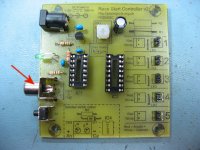
The external switch input can
use either a 2 way 5mm screw terminal (shown left) or a
skeleton phono socket [cinch connector] (shown right)
depending on your preference. |
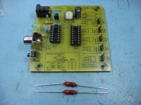
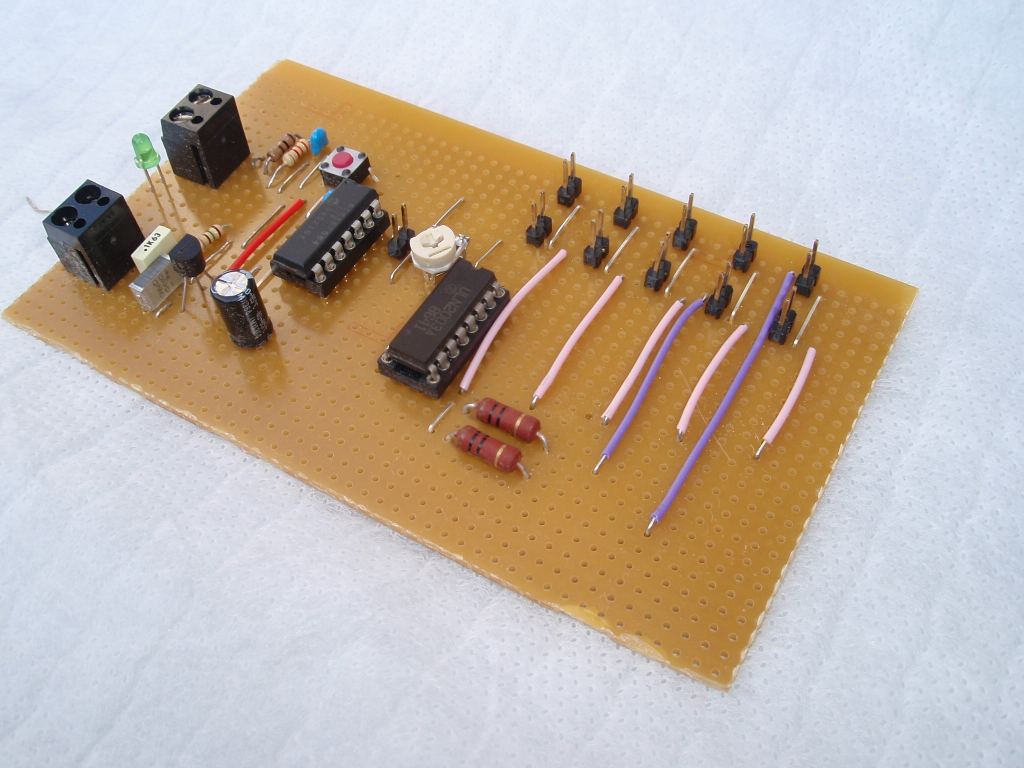
For the LED cluster version
you will need to install R1 and R2. |
After installing R1 and R2 use
the off-cuts from their leads to make the wire links LK2 -
LK5 as shown. |
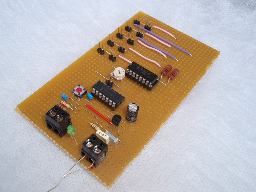
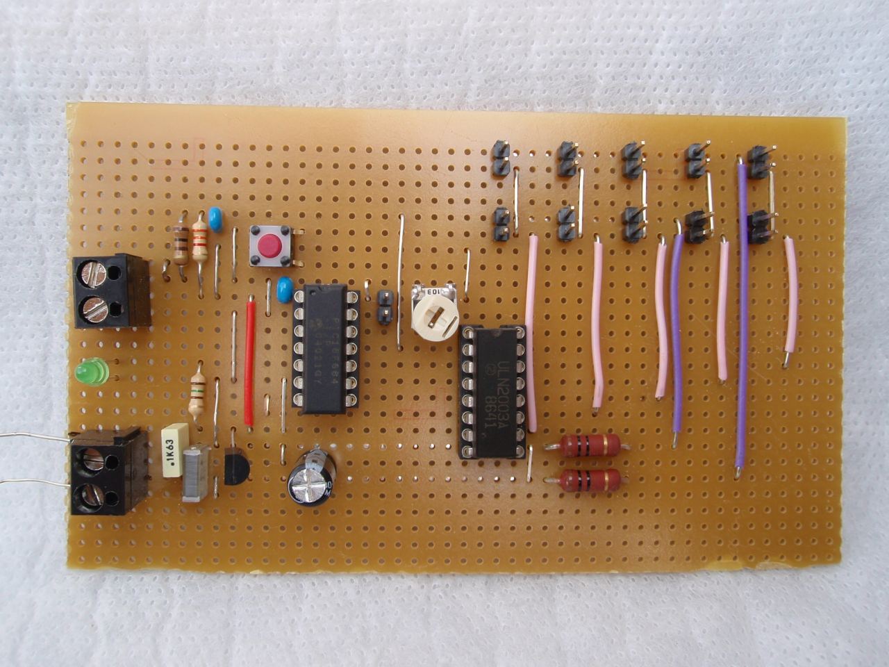
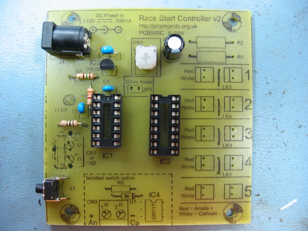
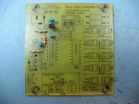
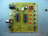
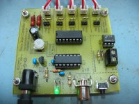
Assembled board for use with
LED clusters. The optional isolated switch input components
have not been fitted.
For the LED cluster version DO
NOT fit JP1 |
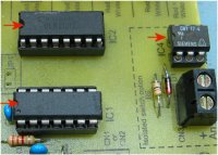
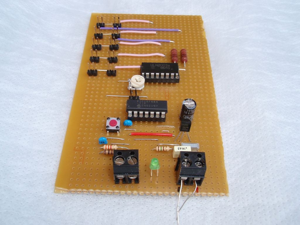
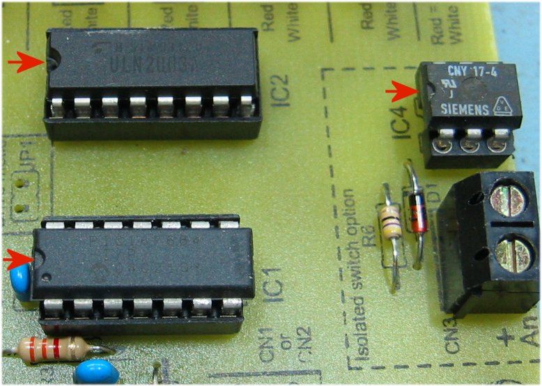
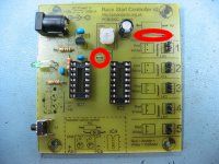
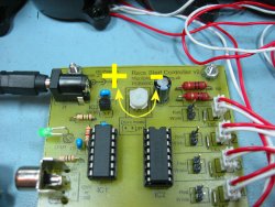
The IC's must be installed
with the small notch as shown.
Also note the black band on Diode D1 |
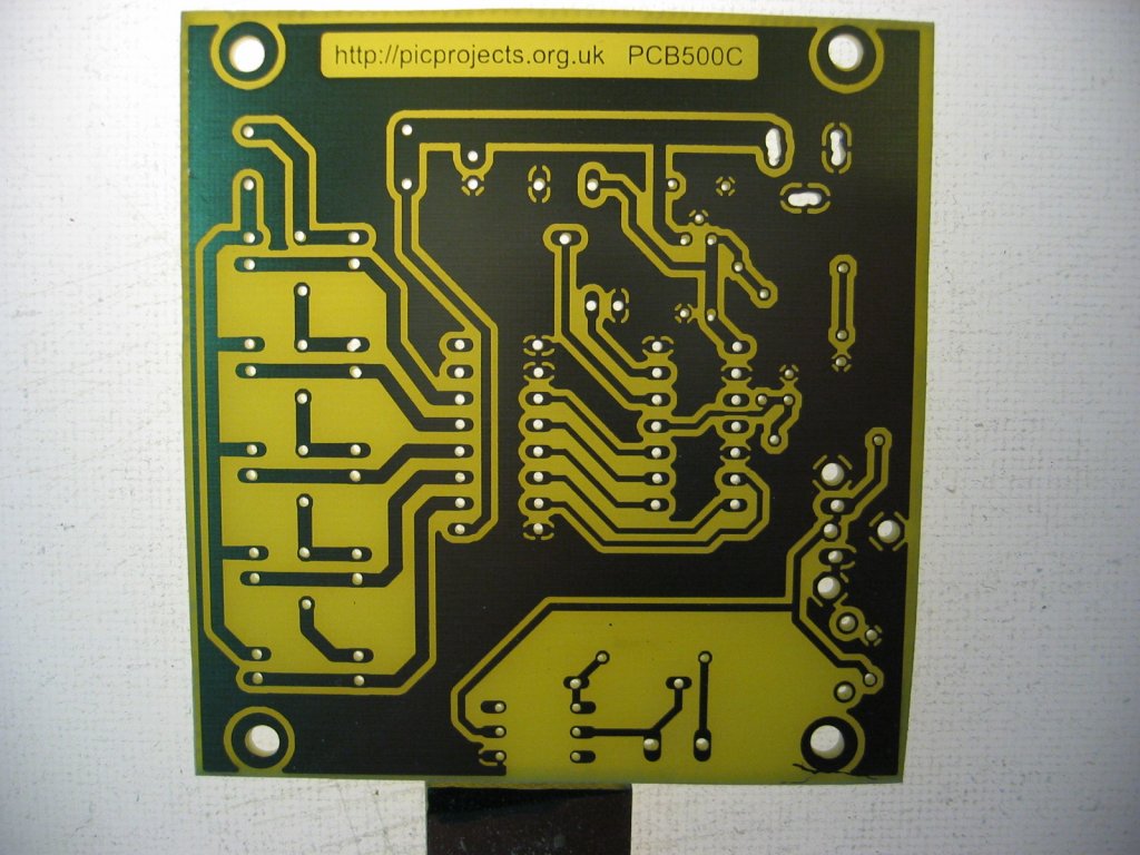
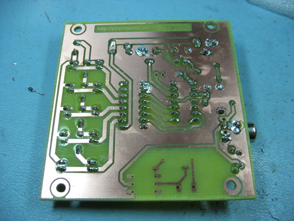
|
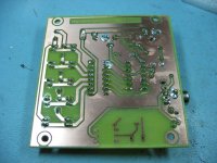
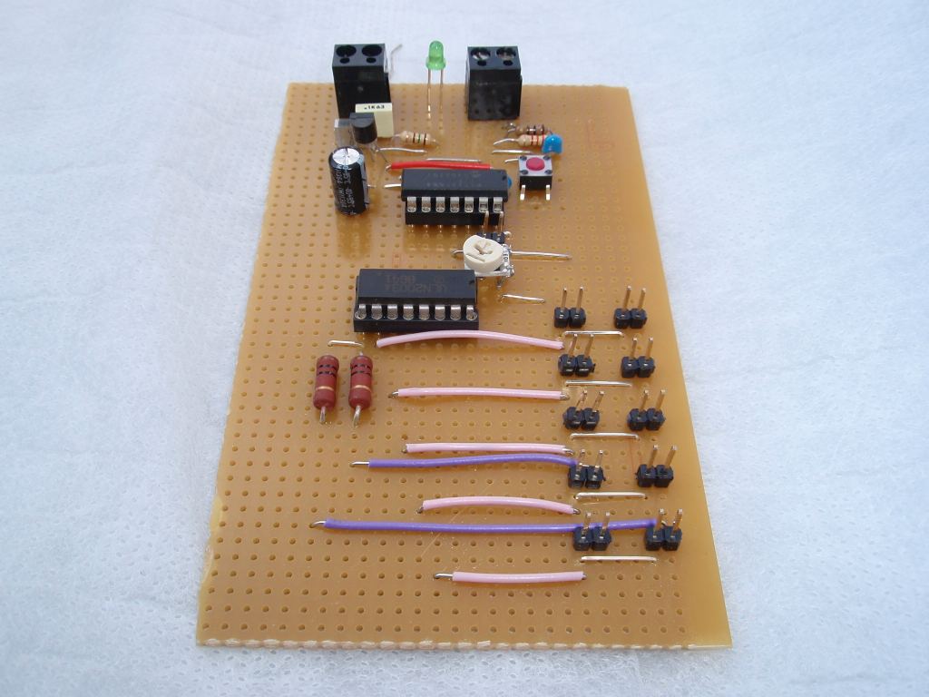
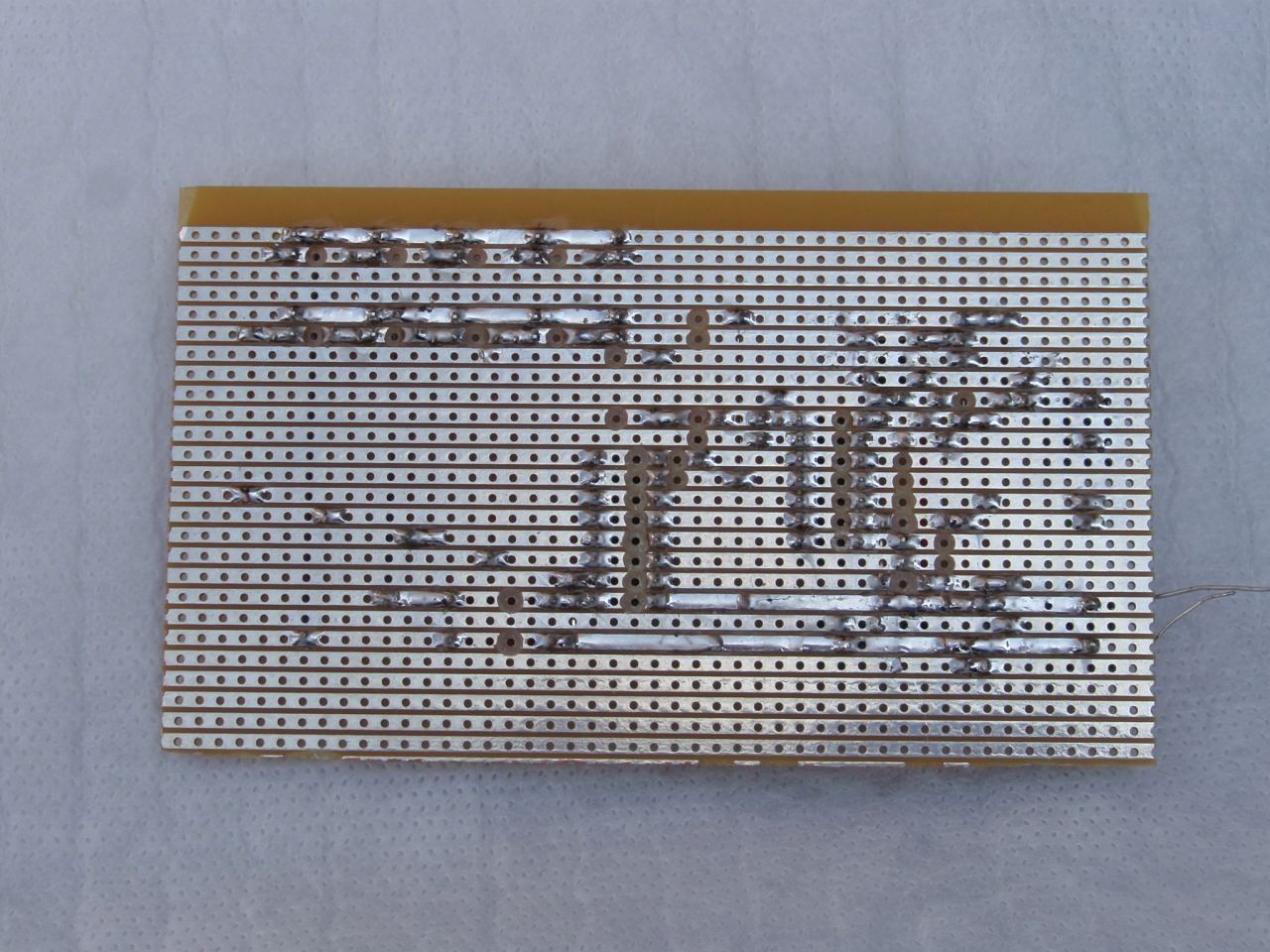
Underside of
the completed board. |
Completed
board with isolated switch input components installed.
Ensure D1 is located with the black band as shown. The
value of R6 needs to be chosen according to the voltage used
in the external input application. |
DC Power input
The board needs a
DC regulated input of 12 volts. Power supply current
rating should be at least 500mA, a 1A supply is preferred.
Do not use an unregulated DC power supply as these generally
only deliver the specified voltage at full load. As the
board has no fuse or over current protection, this should be
provided externally. Typically a regulated DC power supply
will have overload protection built-in and if this is the case
nothing further is required. If you power the circuit from
a battery or other source then you must ensure there is a
suitable in-line fuse.
Switch Inputs
There are two
external switch inputs and an on-board switch. Any of the
switches can be used to operate the unit; you choose which one
depending on your specific requirements.
The on-board
switch is primarily for testing although it can be used for
normal operation if desired. All three switches are
connected to the controller in parallel therefore the use of any
one switch input does not preclude the use of the other two.
SW1 Switch
The SW1 switch on
the PCB can be used for testing the board without any external
switches connected.
The start sequence
is triggered on the release of the switch not the initial press.
Non isolated switch
input
The CN1/CN2
connector provides input for a non-isolated switch to be
connected to the controller.
Isolated switch input option
The isolated
switch input needs its own power source to turn the LED on in
the opto-isolator. If you include the isolated switch
input option you need to select the value of R6 according to the
voltage used in the external circuit.
Suggested values
are shown in the table below. Use a 5% 1/4watt carbon film
resistor. With the values shown the LED current will be
approximately 30-35mA.
|
Voltage (DC) |
R6 |
| 3 |
47R |
| 5 |
100R |
| 6 |
150R |
| 7.5 |
180R |
| 9 |
220R |
| 12 |
330R |
for safety reasons do not
use voltages > 18volts at this input
Right. Testing the board
using the isolated switch option.
The red/black crocodile
clips are connected to a bench power supply.
The isolator will work
with various input voltages provided R6 is correctly
specified (see table above)
|
 |
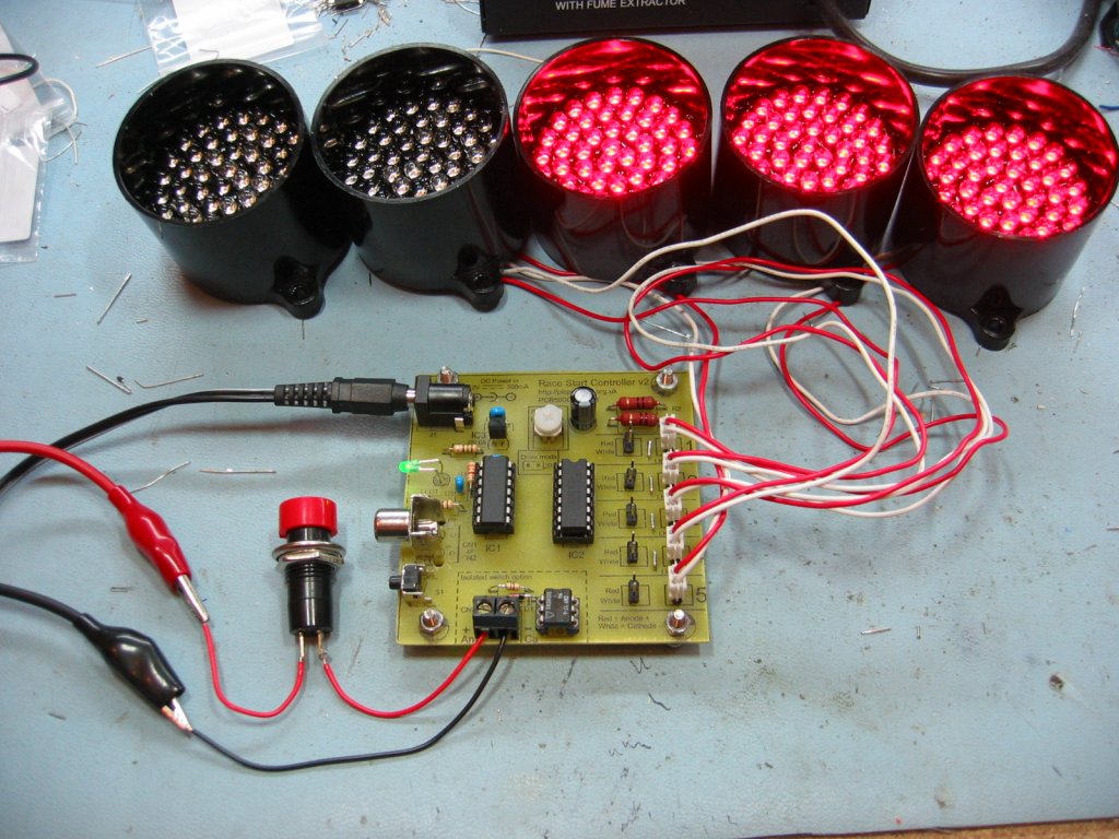
LED Clusters
The LED clusters
are
Kingbright type BL0307-50-44.
These contain 50 LED's connected as 10 parallel strings of 5
LEDs as shown in the schematic below. Available from
Rapid Online - Rapid Electronics Ltd., part No
56-2985
Download datasheet for
Kingbright LED
Cluster

Ensure they're connected to the
controller with the red and white leads as shown in both the
photos and indicated on the PCB overlay. The LED
clusters illuminate sequentially from 1 to 5 and this is
indicated on the PCB overlay.
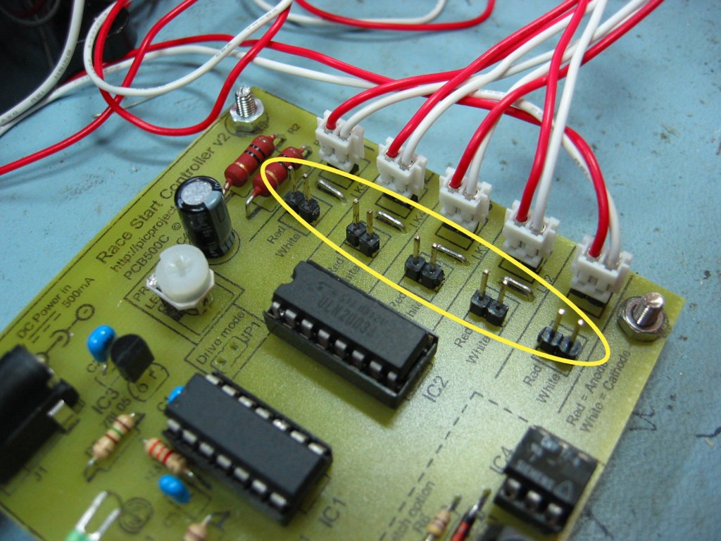
The board will
drive either a single row of 5 LED clusters or two rows.
When using it with two rows, connect the second set of LED
clusters to the second column of 2 pin headers (circled yellow)
in the photo below.
Adjusting
Brightness
When JP1 is open,
the controller drives the outputs using a PWM (pulse width
modulated) signal. This allows the brightness of the LEDs
to be controlled by adjusting the position of PR1. The PWM
frequency is ~350Hz to avoid any visible flickering.
The brightness
control input is an analogue signal varying from 0 volts (dim)
to 5 volts (bright). For the technically minded it is
possible to modify the circuit to use a Light Dependant Resistor
to automatically adjust the LED brightness to match the ambient
lighting.
Drive modes
The software
supports three drive modes of which two are supported on the
PCB. The third mode may be used if you incorporate the
microcontroller into your own hardware design.
The design of the
circuit uses a single current limiting resistor (R1 & R2) for
each row of LED clusters. For this to work only one LED cluster
can be on at any time otherwise the more LEDs that turn on, the
dimmer they get. The software drives each output one at a
time but it does so 350 times a second and through persistence
of vision to the human eye they appear to be on at the same
time. The reason it has been implemented this way is for
two reasons.
-
The total
maximum current required is that of 2 LED clusters rather
than 10 so a smaller and cheaper power supply can be used.
-
The drive
circuit uses a single ULN2003A transistor array and two
resistors which keeps the cost down and the complexity of
the circuit and PCB layout are simplified.
|
Mode |
RA0 (JP1) |
RA4 |
|
|
Direct |
closed (Gnd) |
open |
Use with relays and other devices that can't use PWM |
|
Direct PWM
* |
open |
closed (Gnd) |
Use with LED driver that has individual current
limiting |
|
Multiplexed
PWM |
open |
open |
Use with LED driver that has common current limiting |
The RA0 / RA4 inputs have
internal weak-pull enabled so there is no need for external pull
up resistors.
* On the PCB, RA0 is connected
to JP1 but RA4 is not made directly available since the
Direct PWM mode isn't supported by the hardware on the PCB.
Driving
Relays
If you use the PCB to drive
relays they should be rated for operation at 12V DC and the coil
resistance should be >150 ohms otherwise there is a risk of
damage to IC2 (ULN2003A).
Connect each relay coil to the
2-pin header on the PCB. You'll need 5 relays in total,
one connected to each output.
Also ensure JP1 is closed
otherwise the relays will be driven with a PWM signal and won't
operate correctly.
In the UK all the
components can be obtained from
Rapid Online - Rapid Electronics Ltd.. I've provided a
component list with their part numbers and descriptions. The parts
used are all commonly available and should be obtainable from most good
electronic component distributors anywhere in the world.
Note: where it says
(option)
in the description, you only need
the part if you are building it with the selected option.

| Schematic part |
Qty |
Description |
Rapid Part No |
| LED Clusters |
5(10) |
52MM ULTRABRIGHT
LED CLUSTER (RC) |
56-2985 |
| C1, C3 |
2 |
100N 2.5MM Y5V
DIELEC.CERAMIC (RC) |
08-0275 |
| C2 |
1 |
220N 5MM Y5V
DIELEC.CERAMIC (RC) |
08-0280 |
| C4 |
1 |
100UF 25V LOW
IMPEDANCE ELECTROLY CAP RC |
11-2922 |
| R1, R2 |
1 pack |
PACK 10 10R PR02
2W POWER RESISTOR RC |
62-6708 |
| R3 |
1 pack |
PACK 100 3K3 0.25W
CF RESISTOR (RC) |
62-0382 |
| R4 |
1 pack |
PACK 100 100R
0.25W CF RESISTOR (RC) |
62-0346 |
| R5 |
1 pack |
PACK 100 150R
0.25W CF RESISTOR (RC) |
62-0350 |
| R6 |
1 |
See text
(option) |
- |
| PR1 |
1 |
6MM CERMET
POTENTIOMETE HIGH TEMP 10K (RC) |
67-0354 |
| PWR-ON LED |
1 |
MINIATURE 3MM PURE
GREEN LED (RC) |
55-0107 |
| D1 |
1 |
1N4148 75V 150MA
SIGNAL DIODE. (RC) (option) |
47-3308 |
| |
|
|
|
| IC1 |
1 |
PIC16F684-I/P MICROCONTROLLER (RC)
(Needs programming) |
73-3388 |
| IC2 |
1 |
ULN2003A
TRANSISTOR ARRAY 7 MATCHED (RC) |
82-0618 |
| IC3 |
1 |
DA78L05 V REG +5V
100mA TO-92 TRU (RC) |
47-3612 |
| IC4 |
1 |
CNY17-3 TRANSISTOR
OPTOISOLATOR (RC) (option) |
58-0886 |
| LED cluster plug |
10 |
2 WAY SINGLE ROW
PCB HEADER PLUG (RC) |
22-0520 |
| |
|
|
|
| Socket for IC1 |
1 |
14 PIN 0.3IN DIL
SOCKET (RC) |
22-0155 |
| Socket for IC2 |
1 |
16 PIN 0.3IN DIL
SOCKET (RC) |
22-0160 |
| Socket for IC4 |
1 |
6 PIN LOW
PROFILE IC SOCKET (RC)
(option) |
22-0145 |
| SW1 |
1 |
5.85MM RIGHT ANGLE
TACT SWITCH (RC) |
78-1154 |
| PSU |
1 |
15W MINIPLUG TOP
SM PSU 12V DC 1.2A (RC) |
85-2902 |
| DC Power Skt (J1) |
1 |
2.1MM PCB DC POWER
SOCKET (RC) |
20-0970 |
| CN1 |
1 |
BLACK PCB SKELETON
PHONO SKT (RC) (option) |
22-1122 |
| CN2 / CN3 |
1 |
2 WAY 16A
PCB TERMINAL BLOCK (RC) (option) |
21-0112 |
The PIC 16F684 microcontroller
needs programming before use. Source code and programmer ready HEX
files can be downloaded here.
Download:
Firmware version 1.0.6, release
date 23/05/2008
Not got a programmer? Buy
a pre-programmed PIC from the
On-line store