Description
This project combines a PIC
and three constant current 'buck' converters to produce an RGB LED
controller that will operate with the the high power 350mA LEDs using PWM to control the LED brightness.
By driving the red, green and blue LEDs with varying pulse widths
the controller can generate up to 16 million colours using
fades, strobe and static effects.
The use of surface mount components and the low power dissipation in
the three current sources allows for a very compact design.
The
circuit can drive one or two LEDs in each of the three channels and
will work with devices from Luxeon, Prolight, Laminar, Lumileds and
others.
The project uses a slightly modified version of the
code used for the Standalone RGB controller described elsewhere on
this site allowing the sequence data file to be used from the other
controllers.
As the board uses surface mount components this
project is not really suitable unless you have the soldering skills
and experience to work with this technology.
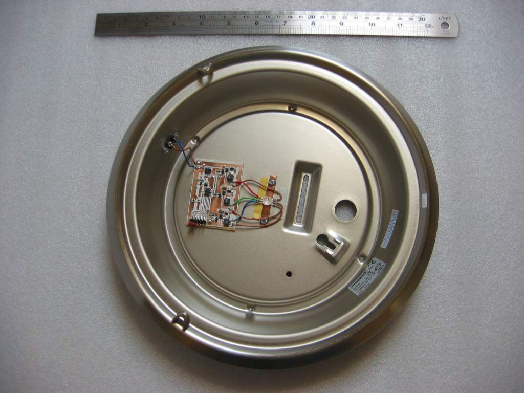
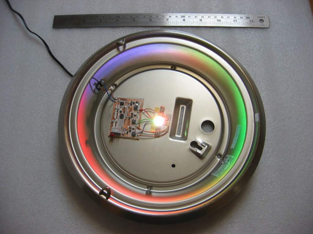
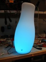
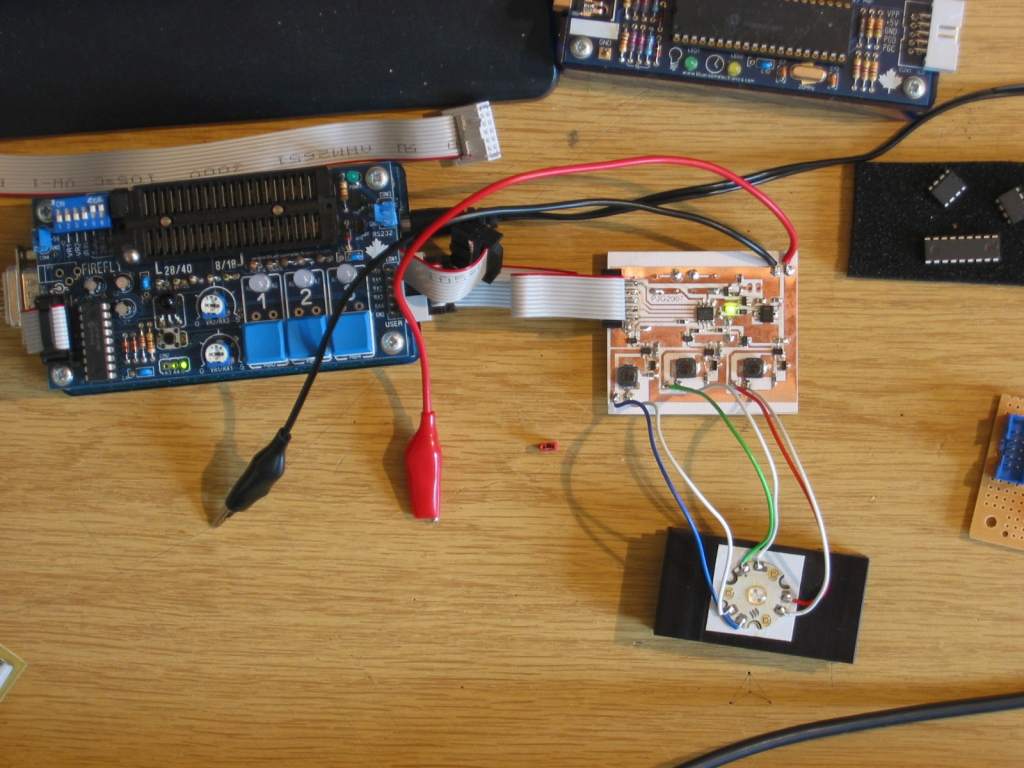
Mood Light
Here we have a mood
light made using the circuit described on this page and a light
fitting I bought from
Homebase DIY store. It's a 26cm metal rim flush light
fitting with brushed chrome finish. The frosted glass dome
diffuses the light from the LEDs while the silver metal base helps
distribute the light evenly.
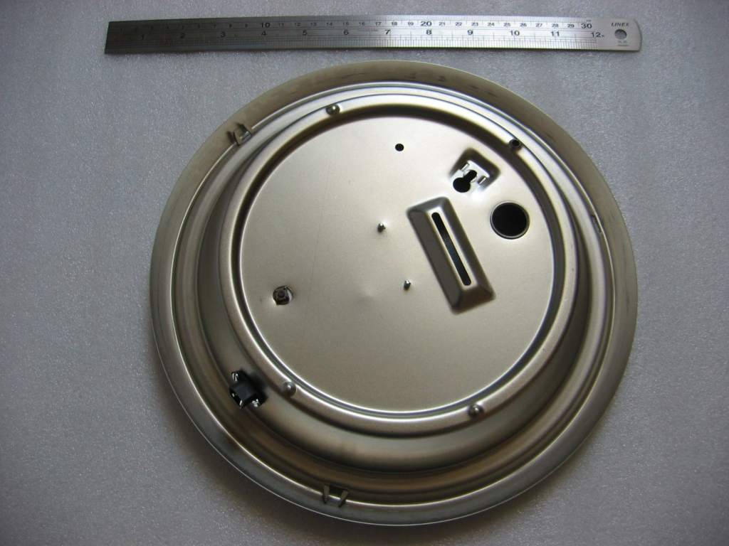
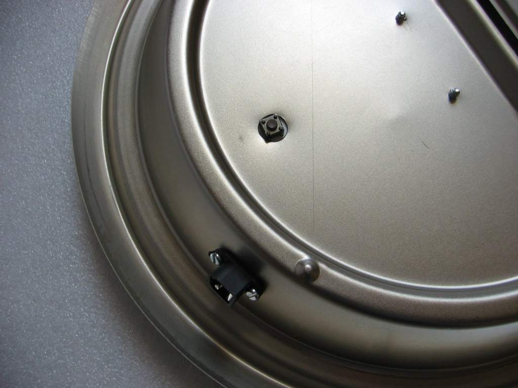
Assembly was kept very
simple. A hole was drilled in the
base for the
'mode' switch to fit through and the PCB was fixed down with double
sided tape. Another hole was drilled and then filed square for the DC
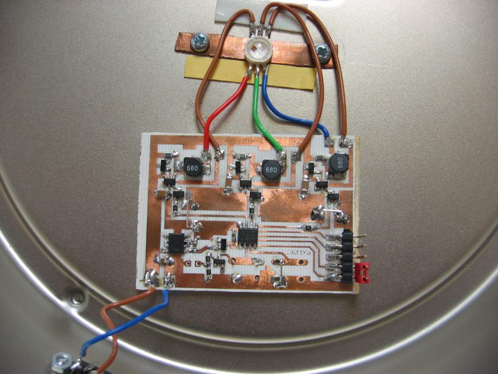
power connector which was secured with two M2.5 screws. The RGB LED came from
www.led-bulbs.com It wasn't fitted to a heatsink so one
was made
from a piece of copper plumbing pipe cut open and flattened; the heat
spreader in the base of the LED was then soldered to the copper.
When the whole assembly is screwed to the metal body of the lamp fitting it
provides excellent heat dissipation for the LED.
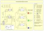
The LED driver circuit is based on
the Zetex ZXLD1350 device. I've basically used their reference
design here so if you have any questions about it the best place to
go is the Zetex website.
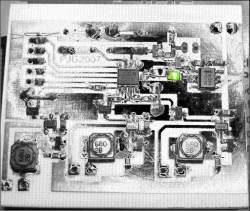
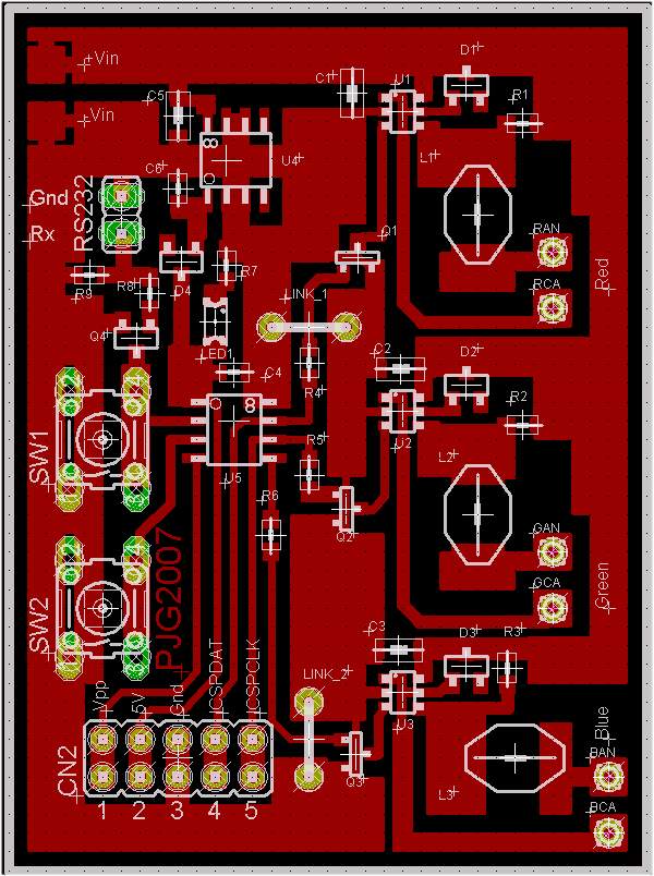
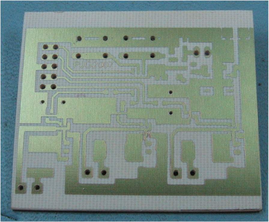
Once you've etched the PCB inspect
it closely, especially around U1, 2 and 3 where the tracks are very
closely spaced, to ensure the board has etched correctly and there
are no copper whiskers between the tracks.
All resistors and capacitors are 0805
sized parts except for C1, 2 & 3 which should be 1206 (you can just
about stretch an 0805 here at a push)
C1, 2 & 3 should be at least 1µF,
larger values up to 10µF
will work. However they should be multilayer ceramic types
using
X7R or X5R
dielectric. Don't be tempted to substitute electrolytic or Tantalum parts.
For further information refer to the Zetex datasheet for the ZXLD1350
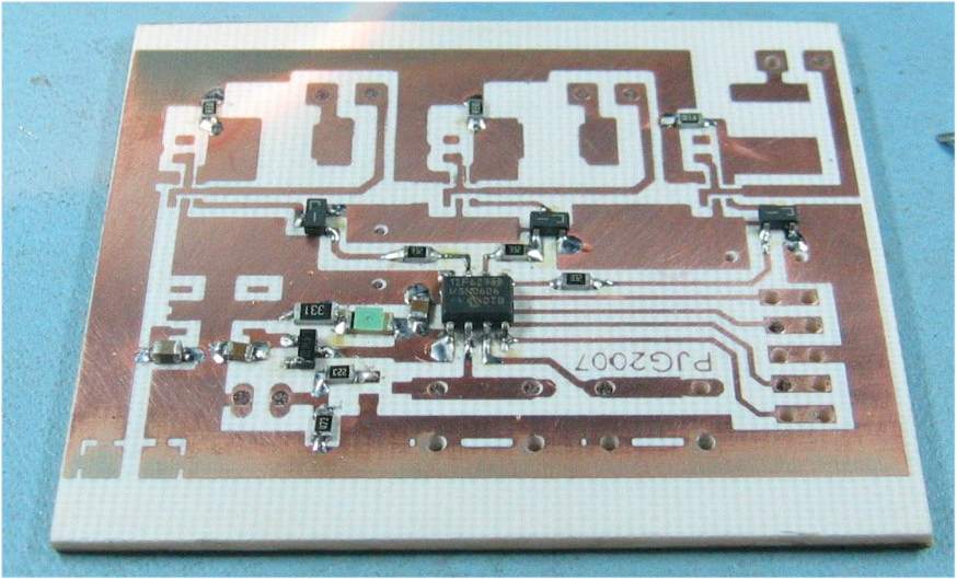
The Zetex ZXLD1350 driver IC and
ZLLS1000 schottky diode are available from
Farnell Electronics
and DigiKey
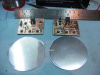
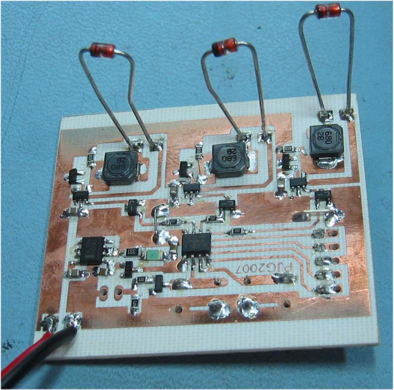
The PCB has been laid out to allow
a choice of inductor to be used. The ones used on the board
shown above were a 68µH Panasonic Part No: ELL6RH680M but you can use any suitable inductor in the range 47µH
to 220µH.
I've built several boards using different inductor types on each
one. Make sure that the inductor is rated for switching at over
350mA and choose ones with low DC coil resistance, ideally less
than 0.7ohm. If you're stuck you can try the following parts
Farnell:
Panasonic Part No: ELL6RH680M, Farnell Order Code: 1198602
Digi-Key:
Panasonic ELL-6PM680M, Digi-Key part No PCD1714CT-ND
I used a BAT54 part for D4, you could
substitute a ZLLS1000 part used in the regulator section here
without any issues. However do not use a BAT54 for D1,2 & 3
Before attaching the LED's I
recommend you test the board with dummy loads. I used 3.3v /
1.3watt zener diodes while I checked the switching circuit was
functioning correctly. This is much cheaper than killing your
RGB LEDs due to a fault or construction error. The base of Q1,
2 & 3 need to be held low for the ZXLD1350 to operate; you can
do this by holding the PIC in a reset state by pulling the MCLR
pin to ground. This will work before the PIC has even been
programmed.
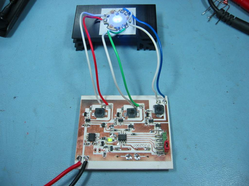
The RGB LED(s) need to be mounted on
suitable heatsinks as they will be dissipating up to 1 Watt each at
maximum brightness. For the single package RGB LEDs where three dies are mounted in a
single package this will require a substantial heatsink.
I've provided two push button
switches and a serial interface. I plan on using these with
future code releases however, with the code provided on this page
only SW1 is used or required. You may wish to omit SW2,
Q4, R8 & R9 parts.
The green SMD LED indicates when the PIC is
powered (either from the ICSP header or the onboard regulator).
It is not essential and you may wish to omit this and R7.
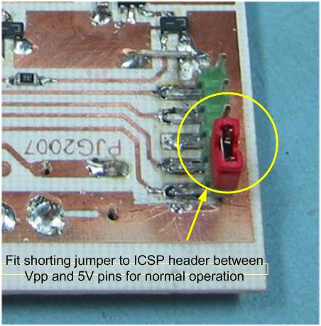
I originally used a single row right
angle header for the ICSP connector and mounted it through-hole on
the reverse side of the board. However, as you can see in the
photo below, I've swapped it for a R/A header tacked vertically onto
the copper side of the board. This keeps the top side of the
board clean except for the switches.