Want to build an RGB LED controller
that you can program with your own custom sequences and effects? Then
read on.
The RGB LED controller has proved to be
very popular project and has been the most frequently downloaded code on
the site since it was made available. I've been contacted by
people who have incorporated this project into all kinds of things
including mood lamps, lighting for a sculpture, accent lighting for
rooms and an illuminated prize trophy.
For 2006 I completely rewrote the
application making it much easier to add, edit and change the sequence
data. I also added a sleep function so a battery operated version
can be built that doesn't need a power switch.
For 2008 I've released version 3 of the
code which now allows you to stop the running sequence at any point so
you can 'freeze' a colour.
All code runs on the 12F629, 12F675 and
the newer 12F683 which, with 2K of program memory has plenty of room for
user sequences.
The original RGB PWM driver application
that I wrote in 2004 had a few shortcomings. Probably the biggest was
that it was not easy to add to or change the sequences. This new
version addresses that problem, is more flexible and now includes the
ability to put the PIC to 'sleep' and 'wake' it again using the sequence
select switch, eliminating the need for an on/off switch in battery
powered applications.
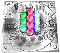
The circuit uses (RGB) Red, Green and
Blue high brightness LEDs that are pulse width modulated (PWM) to vary
the intensity of each colour LED. This allows effectively any
colour to be generated with rapid changing strobe effects, fast and slow
colour fades as well as static colours. The data used to set
and change the colours is held in an easy to edit file so if you don't
like the sequences provided with it, you can modify the sequence data
include file yourself and reprogram with your own sequences.
The code can be assembled for use with
the following PICs: 12F629, 12F675, 12F683. Just select the
correct processor in the MPLAB IDE before assembling.
How bright are the LEDs
That depends on the specific LEDs you
use, the current you drive them with, the angle your view them from
etc........
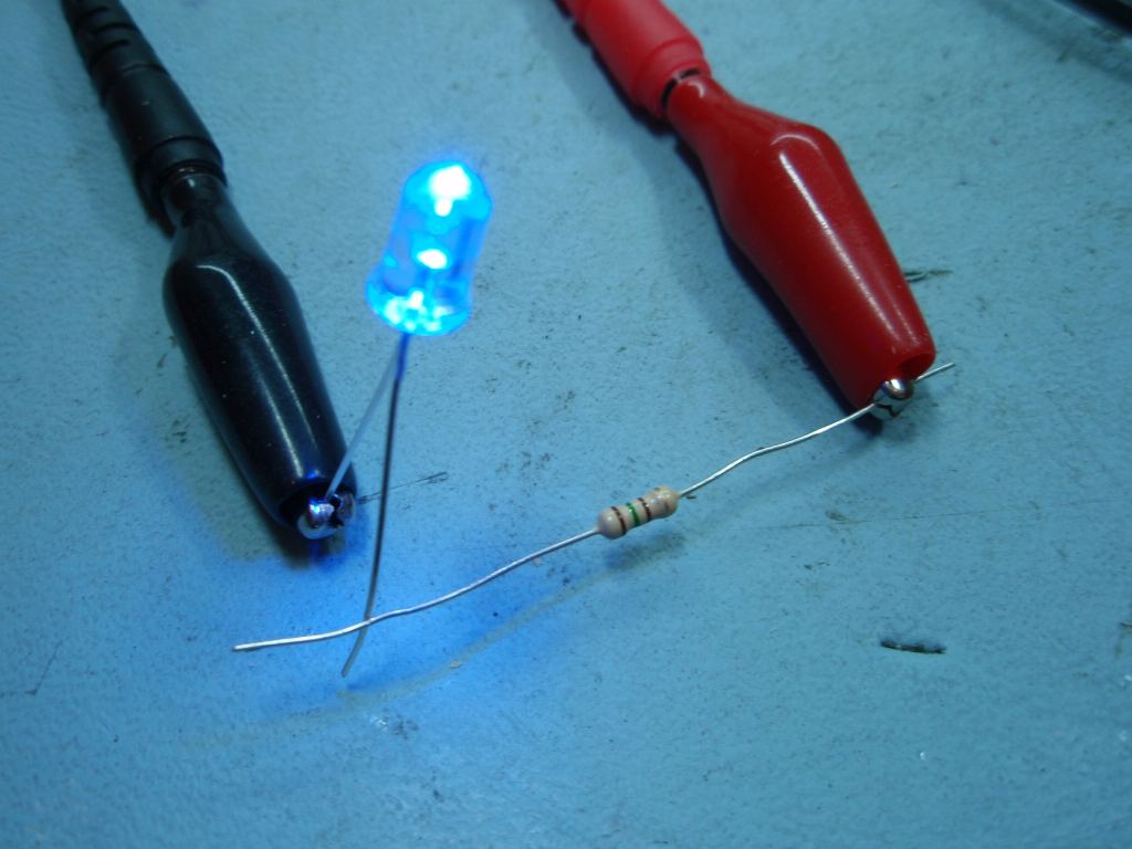
If you want to know I suggest the best
thing to do is buy the LEDs you're planning to use and connect them up
directly to a power supply using a suitable current limiting resistor.
If the brightness meets your expectations than go ahead and build this
project, but if they don't they aren't going to be any brighter in this
circuit so you probably need to look at an alternative solution like a
large array of LEDs driven with the
Power MOSFET Driver project
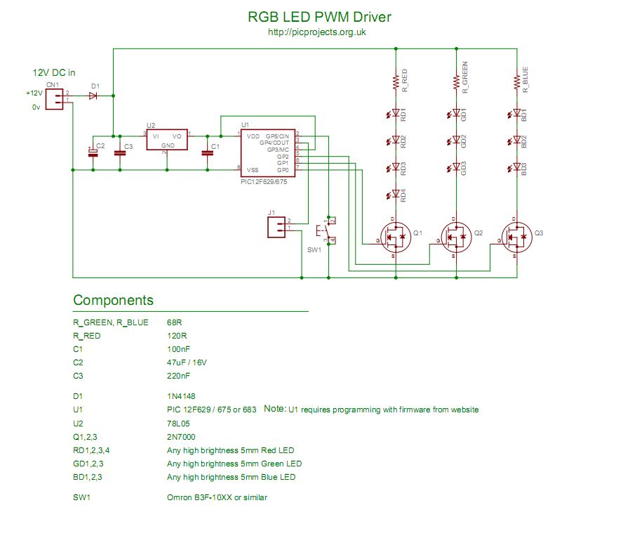
Since I do not know exactly which
LEDs you will use I've specified the LED current limiting resistors
on the conservative side. You may want to change the value of
these resistors to suit the actual LEDs used. Keep the current
per channel to under 40mA maximum.
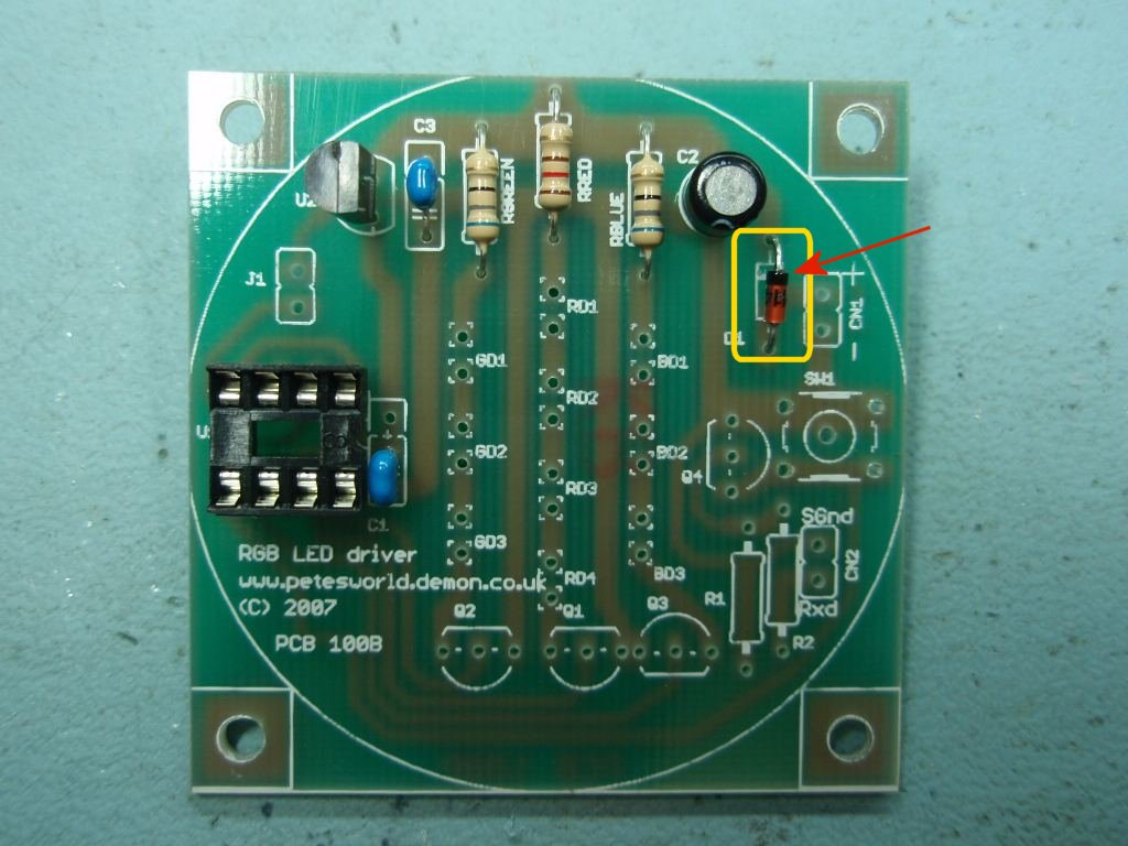
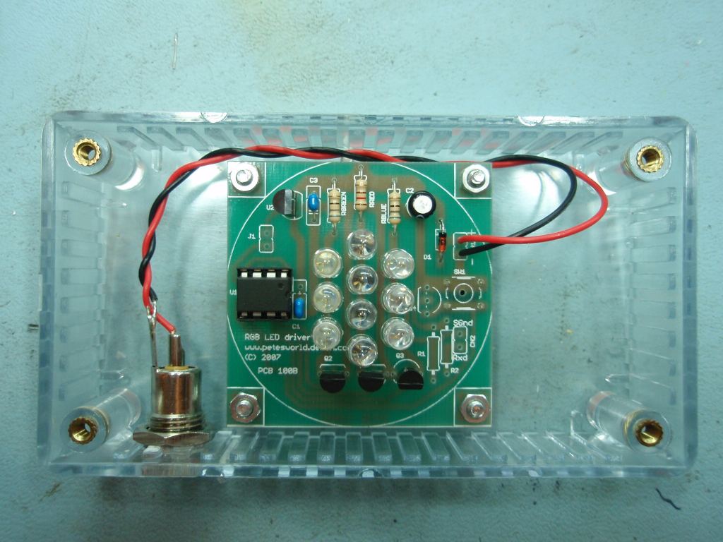
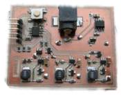
Photo.3 Capacitor C2
must be fitted the correct way round with the negative terminal
towards D1
Photo.4 Diode D1 must be
fitted the correct way round with the band on the diode matching the
PCB overlay.
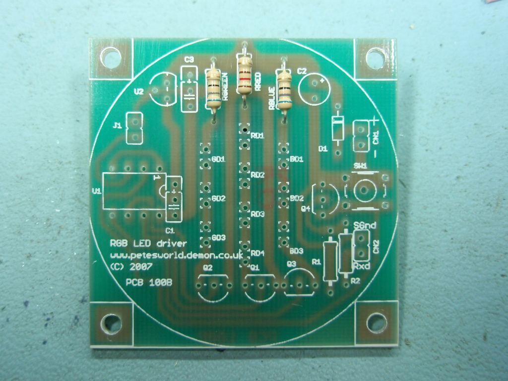
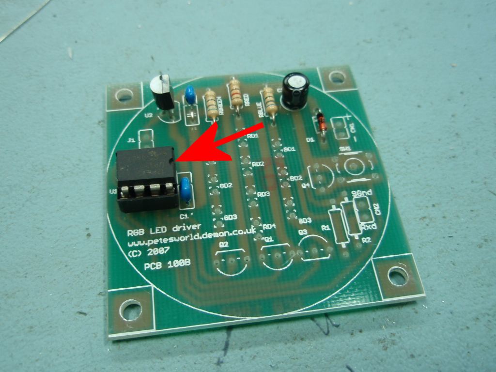
Once you've fitted all the parts
shown in this photo if you have a voltmeter handy it's worth hooking
up a 12V supply to CN1 and checking that 5 volts appears between
pins 1 and 8 of the IC socket for U1.
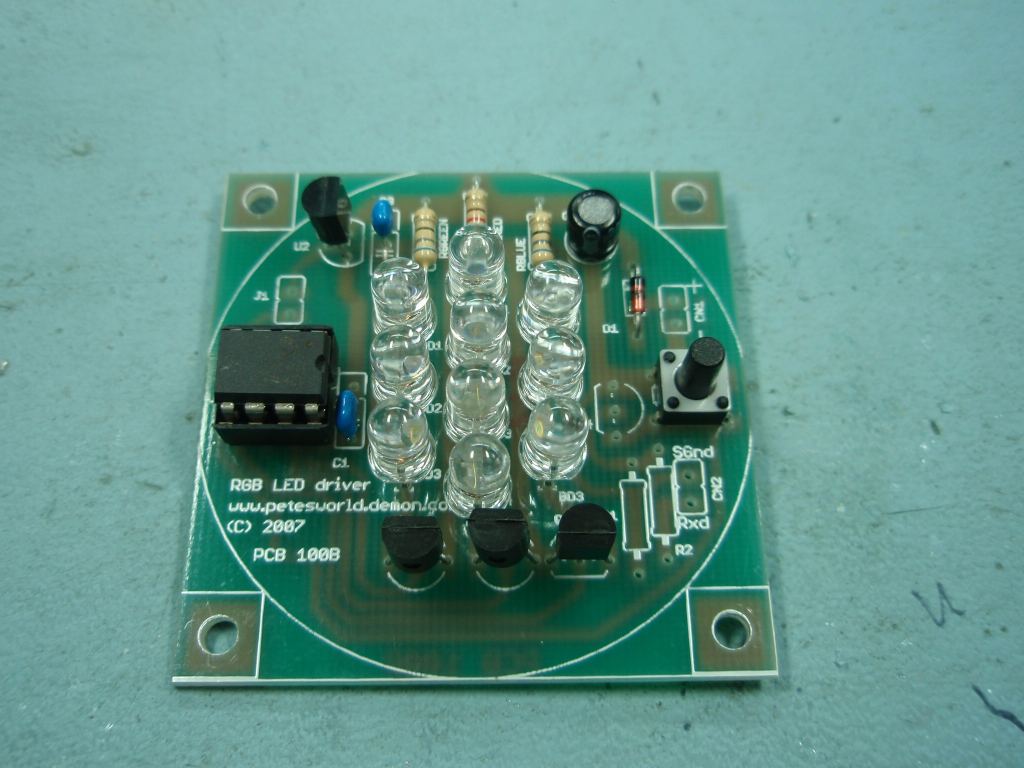
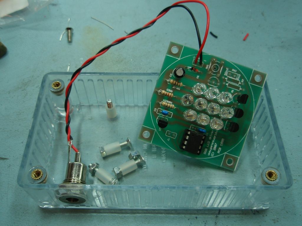
Photo.5 Before
installing transistors Q1,2,3 install the PIC into its socket. It
doesn't matter if you haven't programmed it at this time. (but don't
forget to do so before testing!)
Note the small notch at one
end U1. It must be installed the correct way round, with the
notch towards the centre of the PCB.
Photo.6/7 Install the
transistors Q1,2,3. These are MOSFET devices and are very
sensitive to static discharge so make sure you observe full
ESD (anti-static)
handling precautions.
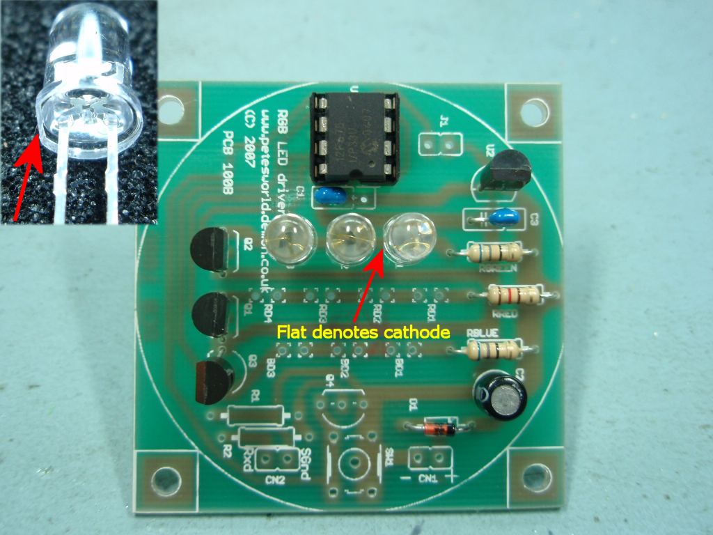
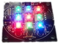
Photo.8 The
LEDs need to be installed the correct way round. The cathode
lead of each LED should be in the hole nearest the transistor
Q1,2,3. The anode lead toward the three resistors
5mm LEDs normally have a flat edge
on the body of the diode and this denotes that the lead nearest to
the flat is the Cathode. This is highlighted in photo.8
It is worth
checking one LED of each colour before installing to make
sure the flat is nearest the cathode for the specific LEDs
you are using. You can do this by connecting the LED
in series with a 150 ohm resistor to a 5 volt supply.
When the LED lights, the lead connected to the 5 volt
negative or ground terminal is the cathode.
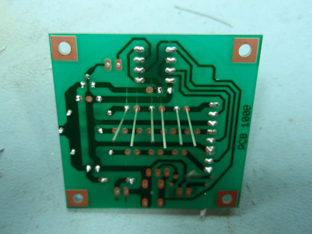
Photo.8/9 Install each
set of LEDs one colour/column at a time. To make it easier to
align the body of the LEDs, solder one lead of each LED. (Photo.9)
Then move the LEDs until they are straight and aligned with each
other before soldering the remaining leads in place. Don't try
aligning them with both leads soldered to the PCB because it may rip
the track off the board.
Photo.11/12 Use the
same method for installing the remaining LEDs.
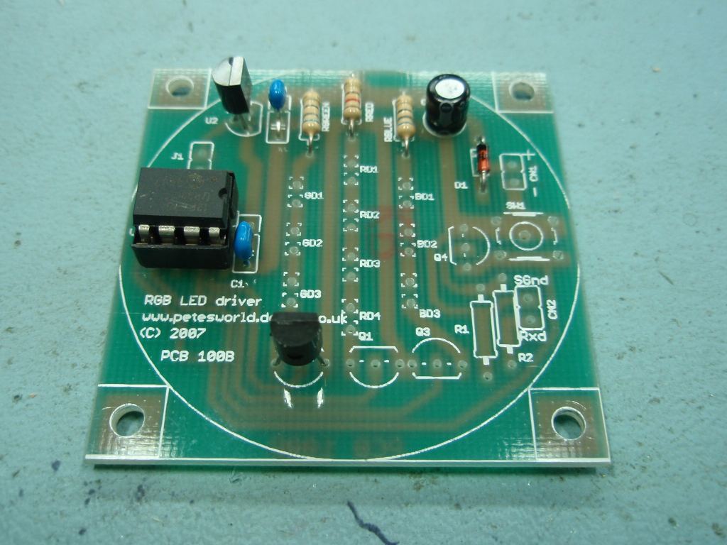
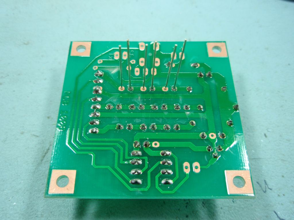
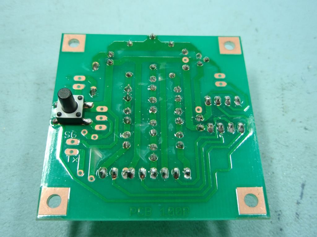
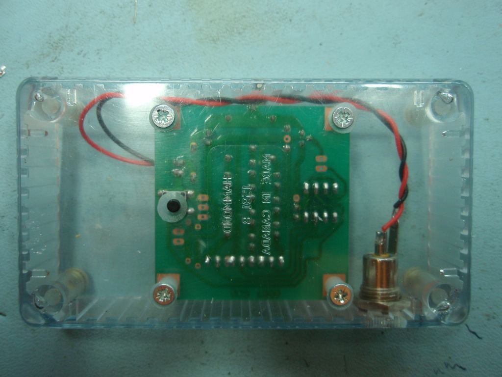
Photo.12/13 Switch SW1
can be installed on either side of the PCB depending on your
application. In Photo.13 it has been installed on the
underside because it will be fitted into a plastic case.
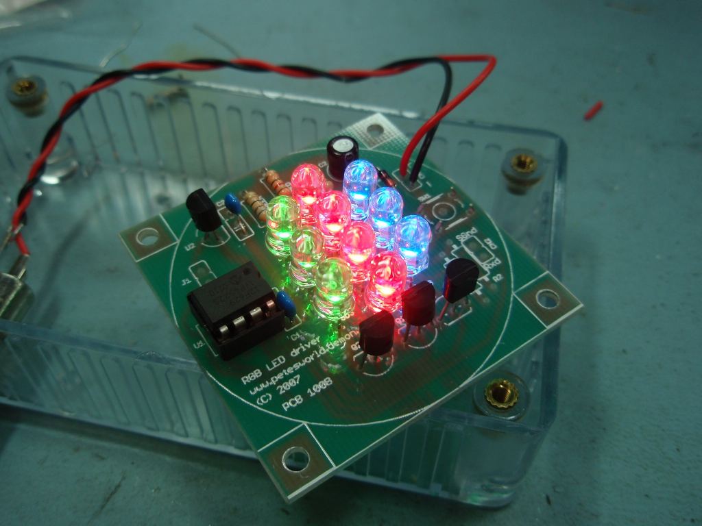
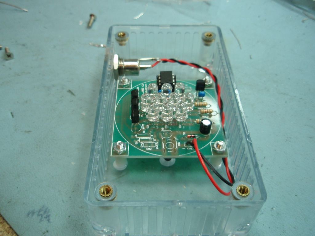
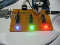
Photo.14/15 Before
assembling the PCB in to a case, now is a good time to test the
board to make sure it's working.
Check the solder joints and
make sure there are no bridges between any of the connections
Make sure you have programmed
the PIC with the firmware code from this webpage.
If any of the LED columns
don't turn off, while others do the most likely cause is a
failed (ESD damage) drive transistor - they usually fail shorted rather
than open circuit.
Troubleshooting. I assume you have some experience of constructing electronic
circuits and have a basic knowledge of electronics and the components
used. The circuit is very simple but if you do have problems
click on the following link for some basic things to test and
check: Troubleshooting page
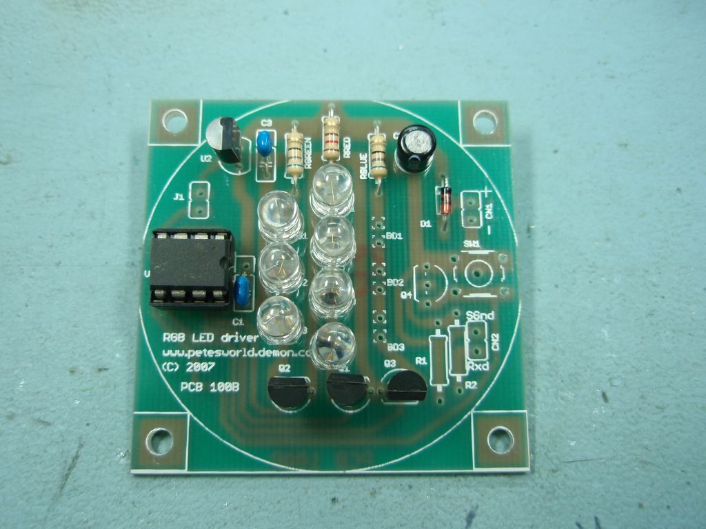
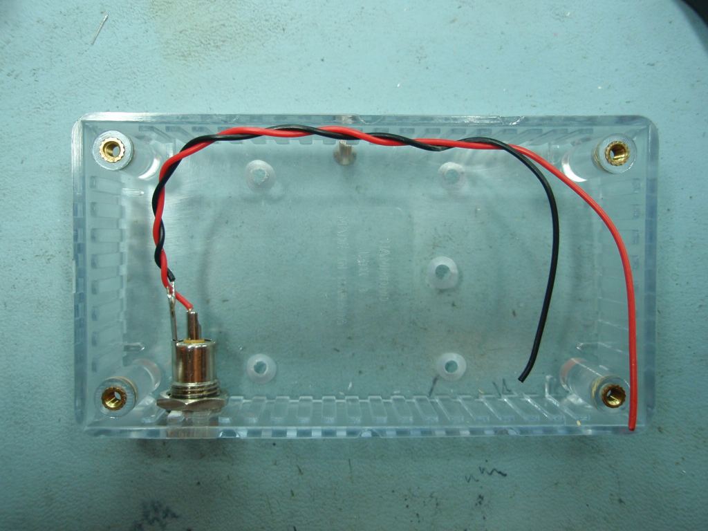
Photo.14-20 You can
use the LED driver for many different applications, some of which
are shown below. For the construction photos' I've
built it into a transparent case (Hammond 1591BTCL 112mm x 62mm x
27mm)
Where to get parts
You can buy the bare PCB or a
PCB + ready programmed PIC from my
online shop
I don't sell complete kits of
parts for this project but you can buy all the other components
needed from
Rapid Electronics. All these parts should be easy to source
from other component suppliers worldwide.
All Rapid parts/descriptions
correct at 2-November-2008. You should check part# and
descriptions are correct when ordering in case I've made a
mistake transferring them onto this page.
Not shown on the schematic
but you may also want to buy
DC Power
connector
NICKEL
2.1MM DC POWER SOCKET (RC)
20-1070
Power supply
5W SWITCH MODE PLUGTOP
PSU 12V 400MA RC
85-2927
PIC Programmer
PICKIT2 STARTER KIT
(RC)
97-0101
* You can also use a 12F675
or 12F683 for U1, the 12F629 is listed because it's cheapest. ** You need 3 x 2N7000
MOSFETs, however I recommend you buy a few extra in case you
damage them during construction.
What LEDs to use
The LEDs listed above are those
I used in the build photo's on this page, however you can use
almost any 5mm high brightness LED with this design.
Your choice of LED's really depends on what you
want to do, how much you want to spend and so on. I've built a lot of
these LED drivers and used various LEDs from different
suppliers. If you use different LEDs you might also
want to alter the values of the current limiting resistors. If you do this
ensure you're operating the LED within the manufacturers ratings
and keep the total current for all three LED colours under
120mA because D1 is only rated to 150mA absolute maximum.
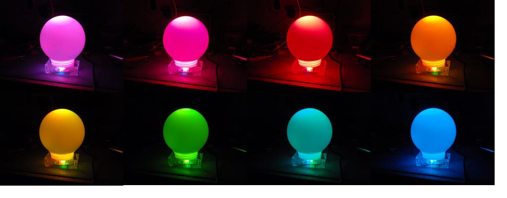
Turn water clear LEDs into
diffused LEDs the easy way.
Almost
all high brightness 5mm LEDs come in a clear plastic
package and have a narrow viewing angle. These are great
for spot effects but for many applications like mood
lamps what you really want
is a diffused LED.
Plasti-kote's glass
frosting spray is a quick and easy way to make clear
LEDs diffused.
I've used the frosting
spray on LEDs with this project and it really improves
the colour mixing effect.
When the PIC is first powered on
after programming, it should start running the first RGB sequence
found. If you're using the original sequences supplied with the code
here it will run a sequence of red-fade out, green-fade out,
blue-fade out repeatedly.
Press the SW1 sequence select
switch to step through all available sequences. When the last
sequence has been reached it will go back to the first available
sequence. Each time the SW1 switch is pressed the RGB LED PWM
values are set back to 0 (LEDs off)
Press and hold SW1 switch for
about 1.2 seconds to put the PIC into sleep mode. Once in
sleep mode, press the SW1 switch for about 2 seconds then release it
to wake the PIC from sleep. If the SW1 button isn't held for two
seconds the PIC returns to sleep - this prevents the circuit from
being accidentally turned on. When operating the RGB
controller from batteries (without a 78L05 regulator) a power on/off
switch is no longer needed since the PIC uses only a few microamps
when 'sleeping'
About 10 seconds after the SW1
sequence switch is last pressed the currently selected sequence
number is saved to non-volatile EEPROM memory. When the RGB
LED driver is next powered on, the saved sequence number is read
back and will automatically start running.
Anytime the PIC is put into sleep
mode by holding SW1 switch down, the currently selected sequence is
also saved to EEPROM.
J1 controls the output drive level
J1 open - outputs are active high
J1 closed - outputs are active low
This feature allows the flexibility
to use the PIC/firmware with alternative hardware designs.
When used with the project
described on this webpage, J1 should be left open.
Because the
firmware code in the PIC simply generates three Pulse Width
Modulated signals it can be used to control almost any LED
driver circuit. I often get asked if it can drive more
LEDs, higher current LEDs etc. To that end the circuit
shown below is a generic driver design that will work
for most applications.
If you want to
drive large arrays of LEDs using the PIC you need to use a logic
level power MOSFET.
Depending on the input voltage and the forward voltage of the LEDs used, you may be able to increase the number of LEDs in
each column. You could also use this type of circuit to
control higher wattage LEDs, but remember the power rating of
the LED current limiting resistor needs to be taken in to
account. (power dissipated in the resistor is = I2R
)
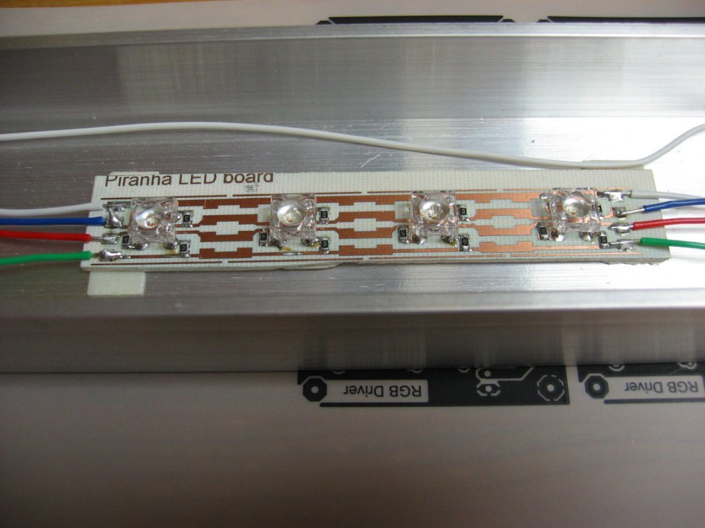
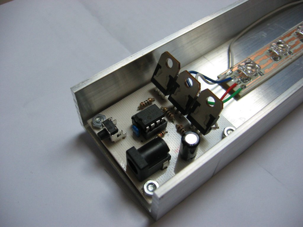
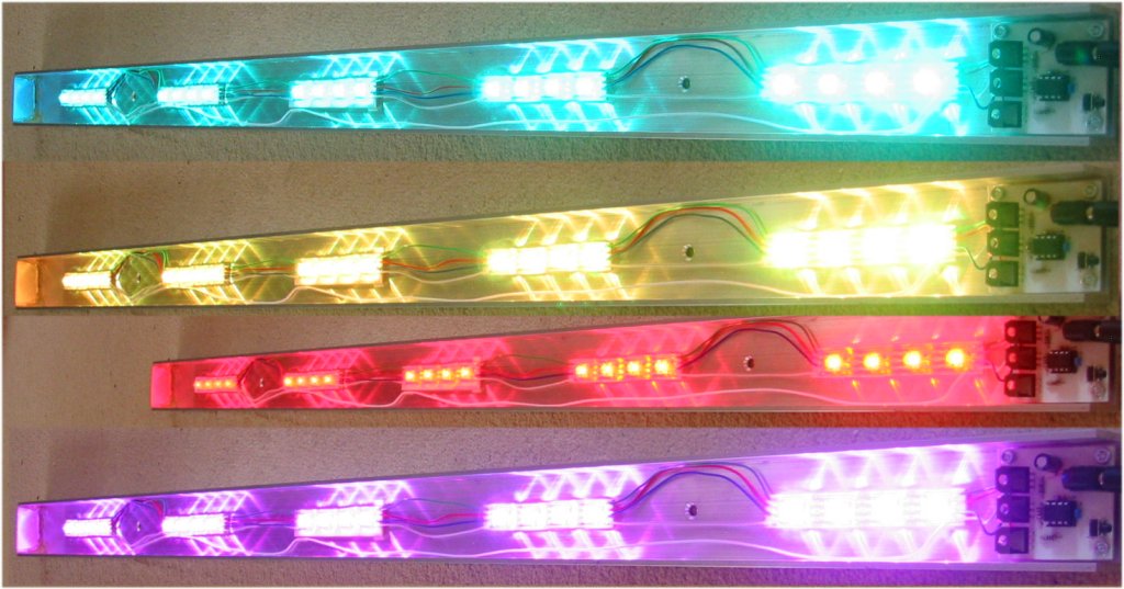
Here's a one off light
bar I built using 20 Piranha RGB LEDs and a custom MOSFET driver
board. Assembled into a 25mm x 50mm x 1000mm aluminium 'U'
section. This was fitted under a wall shelf to illuminate the
floor. It's very bright and gives a nice even illumination
without any additional diffuser. Again this uses the code
available to download on this page
I used 0805 SMD resistors, 68R
for the Red and 47R for the Green and Blue LEDs. Running
from a 5 volt supply it draws about 1.7 amps max.
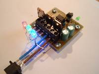
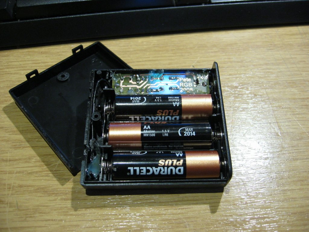
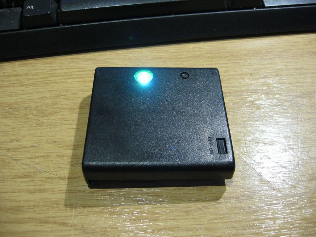
A battery operated
mini RGB mood lamp using Piranha RGB LED.
Housed
in a four AA battery holder, modified to use three
batteries with the PIC and RGB LED controller PCB
located in the space where the fourth battery would
normally fit.
When the
mode button is held for over 1.5seconds the PIC goes to
sleep. When the PIC is sleeping pressing and holding the
mode button for 1.5 seconds will wake the it again so
there is no need for an on/off switch.
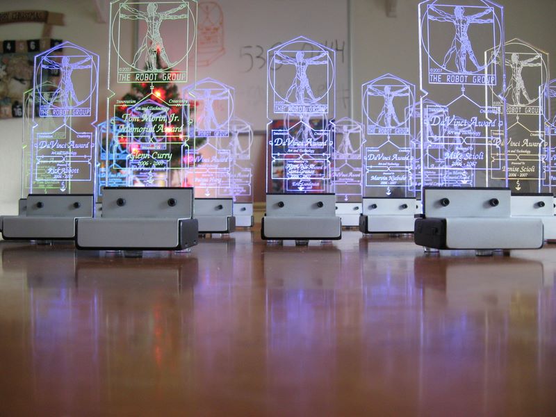
After I
saw these illuminated awards pictured below I couldn't
help but have a go at making one myself. These
were based on my code here on this page.
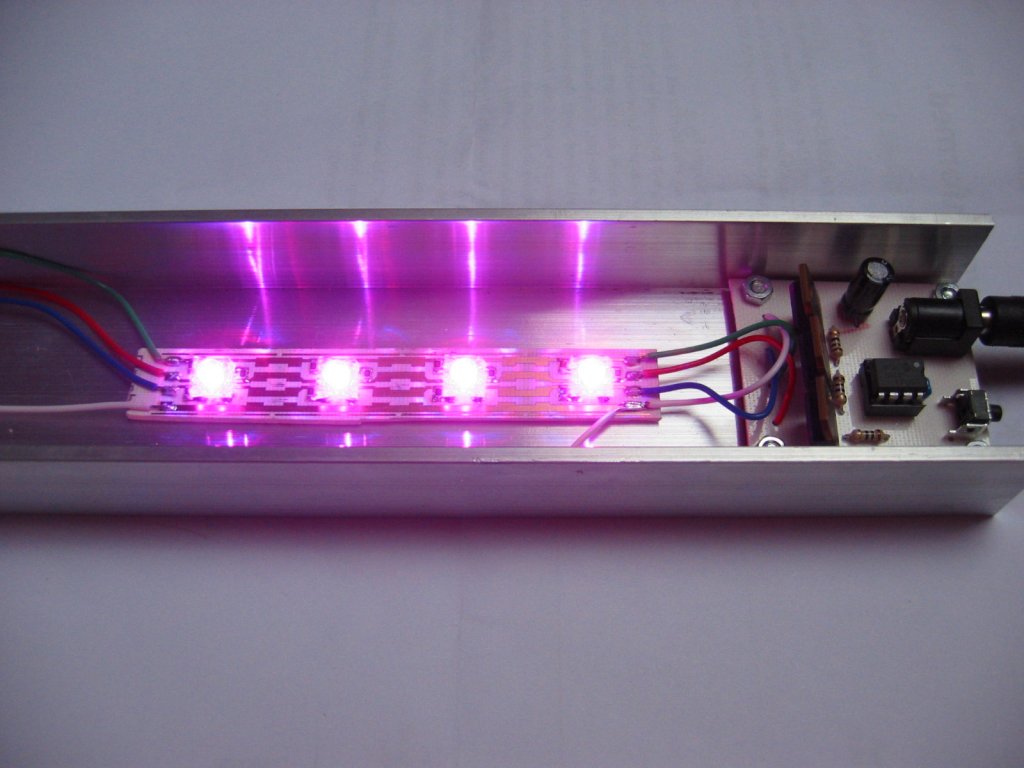
I
bought this light bar from a DIY store. I've fitted four RGB
lights in it and operate it from a 12volt supply.
Image1,
Image2
If you don't want to buy a
programmer you can buy the bare PCB and a PIC ready programmed
with V3 firmware and a selection of sequences from my
online shop.
There are two versions of firmware
available for this project. Version 3 adds a run/hold function
that allows the sequence and colour to be 'frozen' but is otherwise the
same as Version 2. Both versions can be downloaded here and
version 2 will remain available indefinitely.
Full
details and operating guide for Version
3 firmware can be found
here
The PIC microcontroller will need
programming with the firmware below. If you don't already have
a programmer I recommend you buy the PICKit2 from Microchip.
You can buy it from most of the large component suppliers worldwide,
or from Microchip Direct (but shipping is expensive).
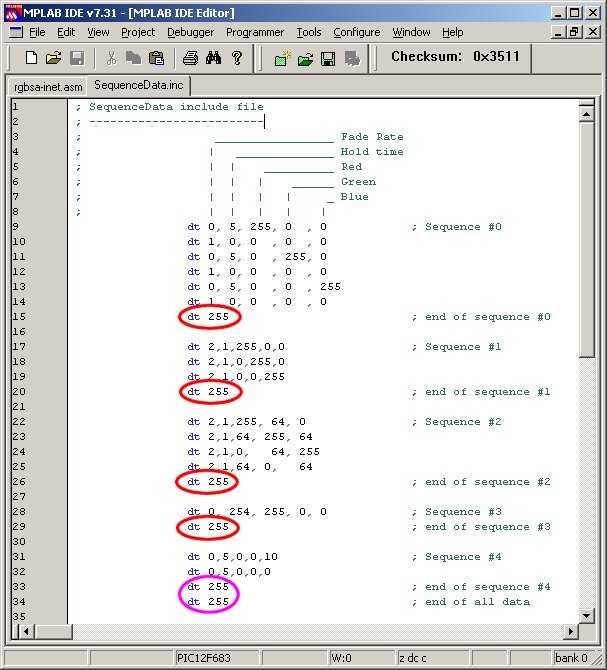
The data
used by the application for the RGB sequences is held in the file 'sequenceData.inc'
You can edit this file to add, remove or change the data provided.
You must ensure that it follows the format described. In
particular pay attention to the 'end of sequence' and 'end of all
data' markers and also ensure that each line of sequence data
contains five comma separated entries. (see screen dump below)
A really useful on-line utility for simulating the sequences can be found
here:RGB
LED Simulator (thanks to Marek 'Marki' Podmaka for creating and
sharing this simulator)
In the
screen dump above note the 'end_of_sequence' markers circled in
red and the 'end_of_all_data' marker circled in
purple.
You must
have at least one sequence present up to a maximum of 256 individual
sequences, although you're likely to run out of available memory on
the PIC before you reach this limit.
Each
line of data starts with a 'dt' (data table) assembler
directive.
All
data is specified using decimal values.
Each data value must be separated
by a comma
The
sequence data on each line has five fields:
Fade Rate: speed the colours fade from the current values to
the new values. Each step occurs at an interval of 5ms x
Fade Rate.
Fade Rate value of 0
indicates the RGB values will be updated immediately
without fading.
Fade Rate value must
not be set to 255 except to indicate end of
sequence. (see e. below)
Hold Time: after fade completes, delay before moving to next
line of data. Interval is 50mS x Hold Time
Hold Time value of 255
following a Fade Rate of 255 indicates
end_of_all_sequence data.
Red PWM
value. 0 = 0% (LED off) through to
255 = 100% (LED fully on)
Green PWM value. 0 = 0% (LED off) through to
255 = 100% (LED fully on)
Blue PWM value. 0 = 0% (LED off) through to
255 = 100% (LED fully on)
Typically changes in LED
brightness are more noticeable between 0 and 128 than from
128 to 255.
End
of the current sequence data is indicated by the Fade Rate field
being set to '255'. When the application encounters this
it restarts the sequence from the beginning.
At
the end of all available sequence data both the Fade Rate and
Hold Time fields must be set to '255'
After
editing sequenceData.inc the file should be saved and the
rgbsa-inet.asm reassembled. The resulting rgbsa-inet.hex
file can them be programmed into the PIC.
I've been working on a constant current
source for 350mA Luxeon type LEDs that can be used with RGB LED PWM
controller on this page and the simple serial controller also on this
web site.
Saving the
Internal Oscillator calibration instruction.
For
details on the internal oscillator calibration word, download the
Microchip datasheet for the 12F629 / 675 and read section 9.2 and in
particular sub-section 9.2.5.1
This
only applies to the 12F629 & 12F675. The 12F683 uses a
different method for calibration
Multiple RGB lights not staying in sync This note follows a
query I had from someone who built these RGB lights. Because
the timing is generated from the internal 4Mhz oscillator and there
is no way to synchronize each device with others, even if they are
running the same sequence, the colours quickly get out of sync with
each other.
If you're building a light bar or any
application where you need more than one unit and they need to stay
in sync you should build the 'serial
controlled RGB driver'.
Oscillator Calibration Instruction
I've had a number of enquiries from
people who can't get the code to work and it has transpired that
they / their programmer has erased the OSCCAL value. Without the
calibration RETLW instruction the code crashes so you must ensure
that it is present or the code will not run.
How
can I recalibrate the internal oscillator on a 12F629 or 12F675?
November 2008
Microchip's
PICkit2 Development Programmer/Debugger has a feature that will
calculate and replace a missing OSCCAL value.
Verify
Errors after programming The RGB light programme code uses
the PICs EEPROM to store the last used mode. When the PIC is
powered up for the first time after it has been programmed it checks
to see if the last sequence value saved in EEPROM is less than or
equal to the number of available sequences. If it is not, the code
resets the value in the EEPROM to 0.
I had a series of e-mails from a guy in Greece who had lots of
problems with "Verify 0000!" errors. I eventually built the
programmer hardware he was using and ran the software to try and
find out what was happening. It turned out that this
particular combination of programmer/software was powering up the
PIC between writing the code into the PIC and verifying it.
This caused the EEPROM to get initialised to "00" but the software
was still expecting "FF" so the verify failed.
The programmer hardware was
PLMS OziPIC'er
and the software was
IC-Prog 1.05D. I must
stress that apart from this idiosyncrasy this is a perfectly capable
PIC programming setup and once aware of what is happening it is easy
to account for and work around.
(A special thank you to Panagiotis
from Athens - thanks to the Internet, his excellent English and much
patience we got to the bottom of this problem despite the language
barrier and the distance)
Editing, adding changing the RGB sequence data.
All the sequence data is now held in the sequenceData.inc file
so it is really easy to add your own sequences. The
application works out how many sequences are present, where they
start and finish and takes care of page boundary crossing. All you
have to do is put the correctly formatted data into the file, save
it then reassemble.
Please take your time when editing the
sequenceData.inc file since errors are likely to cause the RGB
Driver to do unexpected things or crash.
If you see an
'Warning [220]' error during assembly like that shown below, you've
added more sequence data than the PIC has available memory.
Clean: Deleting intermediary and output files.
Clean: Done. Executing: "C:\Program Files\Microchip\MPASM
Suite\MPAsmWin.exe" /q /p12F675 "rgbsa-inet.asm" /l"rgbsa-inet.lst"
/e"rgbsa-inet.err" Warning[220] C:\CODE\RGBSA-INET.ASM 158 : Address exceeds maximum
range for this processor.
If you see an Error [112] message
during assembly check for missing comma separators in the
sequenceData.inc file