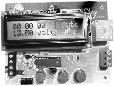
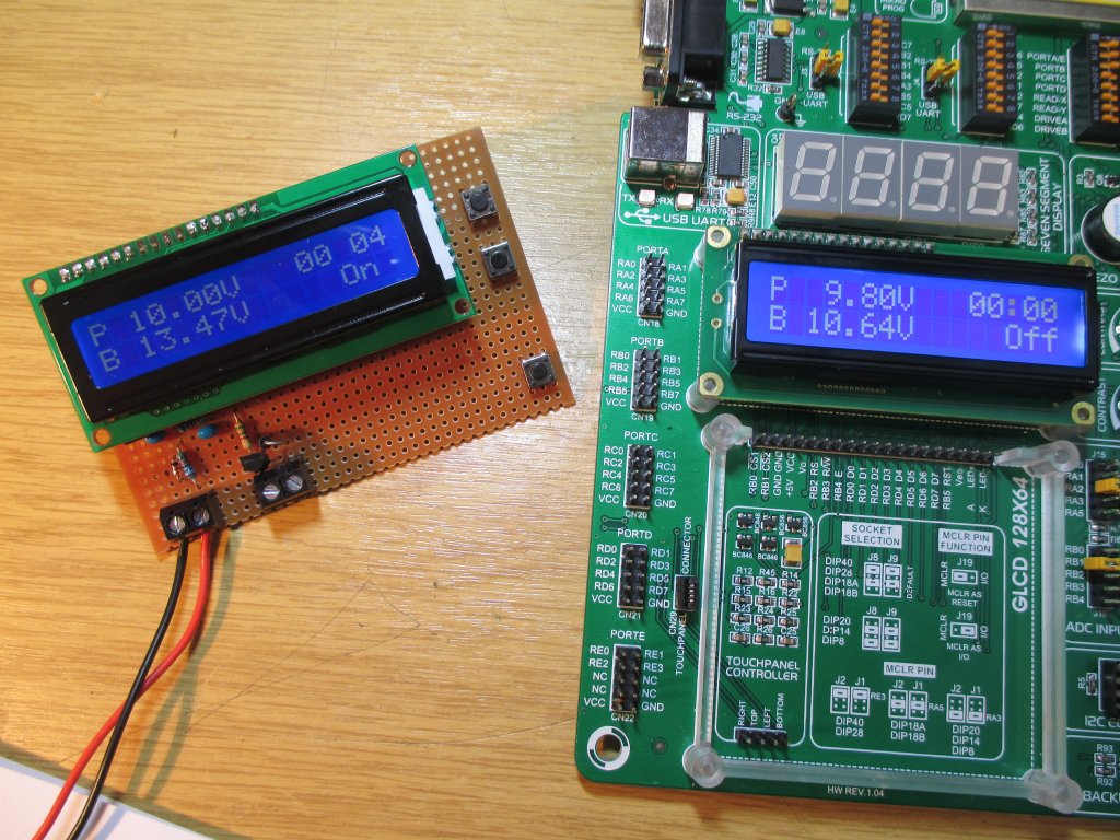
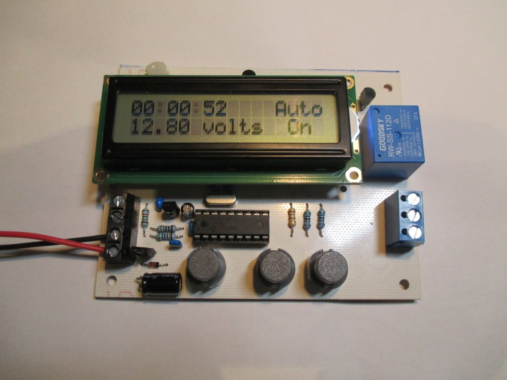
Practical PIC Projects


Low Voltage Disconnect (LVD) Battery Controller(#270)


Description

This project is a low voltage detect / disconnect (LVD) battery controller. The function of the controller is to automatically turn off the load from a battery when the terminal voltage drops below a preset voltage.  This prevents lead acid batteries from being damaged by a deep discharge. It can also be used in other applications where a load needs to be automatically disconnected or reconnected.

This controller project has the following features:

  • On-board 10 amp load relay
  • Controller can be operated from an independent 12 volt power supply, or the battery being monitored (0-16 volt operation only)
  • supply current 7mA to 60mA with relay and LCD backlight active.
  • User configurable options via a front panel menu
  • low and high voltage set points. 
  • automatic or manual load reconnect at the high set point
  • 0-59 second hold off timer.
  • Real time display of battery voltage
  • Elapsed time display shows how long load has been connected (up to 99 hours 59 minutes)
  • Input voltage offset adjustment to compensate for voltage drop in cables (+/- 1.27 volts)
  • Two range modes: 0-16 & 0-32 volts (requires alternate resistors in the voltage input circuit)
  • LCD backlight modes, on/off or automatic.
  • PCB dimensions 80mm x 100mm

Operation

Normal operation

During normal operation the LCD display shows the following information.

The output 'on' timer shows the time elapsed since the output was turned on.  The value displayed is 'held' when the output turns off and resets to 00:00:00 each time the output turns on.

The high voltage preset mode is shown on the top right.  Either 'Auto' or 'Man'

The voltage measured on the input circuit is displayed in real time

The output state is shown on the bottom right of the display.  If it is prefixed with an '*' symbol, the output hold down timer is active.  During this hold down period the output cannot change state again regardless of changes to the input voltage, or in manual mode, user input. 

If the high preset voltage mode is set to automatic and the input voltage is above this set point the load will automatically be connected.  If manual mode is selected the controller always starts-up with the load disconnected

In manual mode, while the input voltage is above the high preset voltage pressing the 'Set' key toggles the output on and off. If the hold down timer is enabled the output can't be toggled again during the hold down period.

When the voltage at the sense input is below the 'low preset' voltage the load output relay will turn off, again subject to the hold down timer being inactive. 

The high and low preset voltages can be adjusted to any voltage, with a minimum of 0.1 volts difference between them.  If either low or high preset is adjusted past the other preset the two presets will automatically track with the adjustment to maintain 0.1 volt difference.  e.g.  If the high preset is 12.50 volts and the low preset is adjusted to 13.00 volts, the high preset will automatically move to 13.10 volts.

User configuration

To enter the setup menu, press and hold the 'Set' key for +1 second.  The first menu item will be shown on the top line of the display.

To scroll through the menu options use the up/down keys.

Options are:

  • Set low preset
  • Set high preset
  • Set input offset
  • High preset mode
  • Backlight mode
  • Hold down time
  • Voltage scale
  • Default all
  • Exit

To select a menu item press the Set key.  The option parameter will appear on the second line of the display.  Change the option using the up or down keys.  For the preset, offset and hold down time settings, pressing and holding the up or down key allows continuous adjustment.

  • Option: Set low preset
  • Parameter: low preset voltage

    - use up/down keys to adjust value in 0.1 volt increments
    - press set key to save and return to menu.
  • Option: Set high preset
  • Parameter:  high preset voltage

    - use up/down keys to adjust value in 0.1 volt increments
    - press set key to save and return to menu.
  • Option: Set input offset
  • Parameter:  real time input voltage with offset applied.

    - use up/down keys to adjust the displayed voltage while measuring the actual battery terminal voltage with a precision voltmeter.   
    - press set key to save and return to menu.
     
  • Option: High preset mode
  • display shows selected option.

    - manual : when input voltage is above preset high volts, load must be manually connected
    - automatic : when input voltage is above preset high volts, load is automatically connected

    - use up/down keys to scroll through options
    - press set key to save and return to menu
     
  • Option: Backlight mode
  • display shows selected option.

    - On : backlight is always on
    - Off : backlight is always off
    - Auto : backlight turns on when any key is pressed, turns off after 15 seconds.

    - use up/down keys to scroll through options
    - press set key to save and return to menu

     
  • Option: Hold down time
  • display shows hold down time in seconds

    - adjustable from 0-99 seconds. 0 means hold down function is disabled.

    - use up/down keys to adjust hold down time
    - press set key to save and return to menu

     
  • Option: Voltage scale
  • display shows selected option.

    - 0-16 volts
    - 0-32 volts

    - use up/down keys to scroll through options
    - press set key to save and return to menu
    (Note: this option requires the resistor divider network on the control circuit board to be fitted with the correct resistor values, this is explained in circuit description)

     
  • Option: Default all
  • display shows selected option.

    - Yes?  : all parameters are set to factory default values
    - No?   : no parameters are changed,

    - use up/down keys to scroll through options
    - press set key return to menu and reset parameters if option 'Yes?' was selected.

     
  • Option:  Exit
  • Press Set key to exit setup menu, there are no parameters.
    - Display shows 'Setup complete' while configuration is saved to Non-volatile EEPROM memory
    - Controller returns to normal operation.


n.b. When the controller is first powered on from new it will display 'Bad config data, Initialising...'  This is normal and once initialised will not display again unless the stored option configuration data has become corrupt.


Connecting up

Connections to the board are shown below


There are two basic configurations to connect the LVD controller.

  • Controller powered from the load battery
  • Controller powered from a separate power supply

Important safety notes:

For safety you should install an inline fuse in the connections between the battery and the load and also the controller.

Do not allow the voltage at the sense input terminals to exceed the maximum range of 16 volts (32 volts if the alternate resistor divider is used)

Do NOT fit JP1 if an external power supply is used, there is a risk of serious damage, or fire if the battery power is connected directly an external power source.

Controller powered from the load battery

  • Minimum voltage when the controller is powered from the load supply is 9 volts.


Controller powered from a separate power supply

  • Operating from a 12 volt dc supply the current drawn by the controller is shown in the table below.
  LCD back light off LCD back light on
Relay off 7mA 22mA
Relay on 41mA 55mA


Schematic

Circuit Description

This section covers how the circuit works, but you don't need to understand it to build a working LVD battery protection controller so feel free to skip it.

The circuit is controlled by IC1, a PIC16F1827 microcontroller running firmware written in MikroC (firmware can be downloaded free)  

The board has separate inputs for the battery voltage sense input and the power supply to the board.

There is a single 10A relay that can switch loads up to 24 volts with Normally open (NO) and Normally closed (NC) contacts presented on a 3-way screw terminal

The controller requires a 12 volt DC power supply to operate.  For applications where the control board will be powered by the battery being monitored, there is a jumper (JP1) that can be fitted to link the power input with the monitoring input.  The main circuit and display require a 5 volt supply which is provided by IC2, 78L05 regulator.  Diode D2 protects the board from reverse polarity protection of the power input.

The actual power supply voltage to the board can be in the range 9-15 volts.  The Goodsky RW-SS-112D load relay is nominally rated for 12 volt operation but will operate with supply between 9 and 15 volts.  Equivalent relays from other manufacturers will typically have a similar operating voltage range but check the datasheet to confirm this.

Output relay

The output relay is controlled by transistor Q1.  Diode D1 clamps the flyback EMF from the relay coil when it is turned off.  Although the relay contacts are rated for operation at AC mains voltages, the PCB layout does not have the necessary isolation to operate above 24 volts.  If you will be using the board with loads above 5 amps up to the full 10 amp rating of the relay, solder additional load carrying solid copper wire over the PCB traces (this is shown in photographs in the construction section)

The Goodsky RWH-SS-112 is rated at 15 amps and is a straight swap for the 10 amp RW-SS-112.

Voltage sense input

The monitored input voltage is fed to the microcontroller via a resistor divider network comprising R2+R3/R4.  The resistor values for the 0-16 volt range have a ratio of 4:1 while the 0-32 volt range uses 8:1.  For precision it is important to use 1% tolerance resistors.   The microcontroller uses an internal 4.096 volt precision reference and 10-bit analogue-to-digital (ADC) convertor to measure the battery voltage.  The input is sampled every 50mS and fed through an 8 point rolling average before being displayed.

  • For 0-16 volt range, resistors R2 = 15K0 and R3 = 1K80 (total 16K8)
  • For 0-32 volt range, resistors R2 = 33K0 and R3 = 6K20 (total 39K2)

    - for precision these need to be 1% tolerance.
    - we used two E24 resistors values in series to obtain the exact resistance needed as they are can be easier to obtain.

LCD display

The LCD display is a standard 2x16 HD44780 compatible display.  PR1 adjusts the display contrast.  If there is no display when the controller is first used, try adjusting PR1 through its full range.  For displays with a backlight transistor Q2 is used to turn it on and off under control from the microcontroller.  The backlight LED current is set by resistor R6.  A value of 180 ohms was chosen for this but you may need to alter it to accommodate displays from different manufacturers.  Don't go below 68 ohms.

Microcontroller

The microcontroller used for this project is a PIC16F1827. A external 4MHz crystal, XT1 provides the clock signal for the microcontroller and should allow the elapsed timer function to give an accuracy of better than +/- 5 seconds in 24 hours.  The actual controller on this webpage only stayed within 1 second over a 92 hours test.


PCB Artwork and Overlay

Download artwork in PDF
Download artwork (Mirrored) in PDF

Download component overlay PDF

I've designed a single sided PCB for this project, however it's a very simple circuit with minimal components so there is no reason why you couldn't build it on stripboard.

In fact, the first prototype I made was done exactly like this as you can see in the photo -->


Component List

You can buy all the parts needed to build this project from most component suppliers world wide. In the UK you can get everything from Rapid Online and I've included a parts list with their part numbers below.  This list does not include the PIC16F1827 which you can buy pre-programmed from Picprojects online shop


All Rapid parts/descriptions correct at 10 October 2014.  You should check part# and descriptions are correct when ordering in case I've made a mistake transferring them onto this page.

Qty Description Part #
1 560r Cr25 0.25w Cf Resistor - Pack of 100 (Order 1 pack only) 62-0364
1 180r Cr25 0.25w Cf Resistor - Pack of 100  (Order 1 pack only) 62-0394
1 15k 0.25w Metal Film Resistor - Pack of 100 (Order 1 pack only) 62-0907
1 1k8 0.25w Metal Film Resistor - Pack of 100 (Order 1 pack only) 62-0842
1 5k6 0.25w Metal Film Resistor - Pack of 100 (Order 1 pack only) 62-0867
1 10k Wr-085 Carbon Preset Potentiometer 67-0412
2 27pF +/-5% 100V NPO P:2.54mm Suntan Radial Ceramic Capacitor 11-3403
3 0.1uF +/-10% 100V X7R P:2.54mm Suntan Radial Ceramic Capacitor 11-3442
1 100µF ±20% 35V 105°C 2000 hours Suntan Radial Aluminium Electrolytic 11-3525
1 Forever 85°C 2.2U 50V Radial Micro Miniature Electrolytic Capacitor 11-0860
1 4.00mhz Hc49/s Crystal +-20ppm 90-1074
2 1N4148 75V 200mA signal diode 47-3309
2 Bc639 Tran Npn 80v 1a To92 81-0080
1 a78l05 V Reg +5v 100ma To-92 Tru 47-3612
1 12V RW Series 10A SPDT Relay 60-4662
1 16x2 FSTN Black on White LCD Display Wide Temp 80x36mm8 Pin 0.3in Turned Pin Socket 57-2382
1 18 Pin 0.3in Turned Pin Socket 22-1723
2 2 Way 16A Black Interlocking Terminal Block 21-0440
1 3 Way 16A Black Interlocking Terminal Block 21-0442
1 20 Way Turned Pin SIL Socket 22-1750
1 20 Way Turned Pin Sil Header 22-1704
1 2 Way Single Row PCB Header Plug 22-0520
1 Miniature Open Jumper Link 22-0692
3 D6 Round Grey Keyboard Switch 78-0175

Parts List Notes

You can download the above list as a text CSV file that can be cut & pasted into Rapidonlines quick order form  csvpartlist.txt

IC1, PIC16F1827 microcontroller is not listed above as Rapidonline don't currently sell it.  You can buy the pre-programmed part from Picprojects - click here


Construction photos:

A brief photographic guide to PCB assembly and testing.  We assume you have some knowledge of electronics and can identify the components.  Also a good level of soldering skill.  Please read through before starting assembly as there are some important things to note. 

Make sure to reference the component overlay PDF to see where the components need to be fitted.

Copper side of PCB after etching and drilling

Component side of PCB after etching and drilling. 


Resistors and diodes installed. Make sure to fit the diodes with the black band towards the arrows.

General assembly tip is to install the components with the lowest height above the PCB irst and work your way up.

Close up of R2/R3/R4 and D2.  Note the coloured bands on the resistors and make sure to fit them in the correct positions on the PCB.

Resistors shown are for the 0-16 volt version of the controller.


Close up of R1/R5/R6

General view of the board


General view of the board


This photo shows the assembled board.  Note the orientation of transistors Q1/Q2 and voltage regulator IC2.

Also the two electrolytic capacitors C3/C4 - these parts have one lead shorter than the other.  The short lead is the negative terminal, it is also marked on the body of the part.  Be sure to fit it as shown.


C3 is positioned on its side to keep the profile low

Now the board is assembled it is a good idea to check the 5 volt supply to the IC1 socket before inserting the microcontroller. 

Connect a 12 volt supply to the 'ext power' screw terminals.  Best not to use an large battery for this since it will deliver enough current to cause series damage if there is a fault.

Using a voltmeter, measure the voltage between pins 5 and 14 of the socket.  If its between 4.9 and 5.1 volts all is good.


Tin the copper tracks between the relay contacts and the screw terminal block with solder as shown.  This will carry about 5 amps. 

If the relay will be switching the full 10 amp rating, add some solid copper wire over the PCB tracks as shown above.


The microcontroller, IC1, must be fitted the correct way round. There is a semi-circular mark at one end.  Fit the IC in the socket with this mark at the end marked by the arrow as shown above.

Assembled board with LCD display attached.  This is running from an external 12 volt power supply, JP1 is fitted so the sense input is monitoring the power supply voltage

You will need to get some 2.5mm screws and spacers to securely mount the LCD display onto the PCB


Did I mention fuses?  Well I'll say it again, Use Fuses at the battery end of the connecting cables. 


Firmware

The firmware is for use with a PIC16F1827 microcontroller.

The HEX file is ready to program straight into the PIC. 

The 'C' source code was written using MicroC PRO 6.4.0  You can download the free version of the C compiler from the MikroElektronika website - however, this is limited to a compiled program of 2K maximum and this program uses about 2.5K so you won't be able to modify and recompile it unless you edit out a lot of features.

Not got a programmer?  Buy a pre-programmed PIC from the On-line store

Description Filename Download link
Source code for 16F1827 LVD270B_V11.c download
HEX file ready to program into the PIC
for use with
16F1827
LVD270B_v11_4568.HEX
Version 1.1 11/10/2014
Checksum 0x4568
download

PIC16F1827 configuration words are set correctly in the HEX file but should your programmer need them they are: CONFIG1: 0x0FDA CONFIG2: 0x1213


If you need a PIC Programmer I strongly recommend the Microchip PICKit 2, this is available from suppliers world wide or direct from Microchip.  It's reasonably cheap to buy and reliable. 


Contact us: