If you're going to use PICs' whether it's with code written by someone else, or with your own code you'll need a programmer. There are numerous free hardware designs available and the software to control them. Alternatively you can buy programmers as kits or ready built.
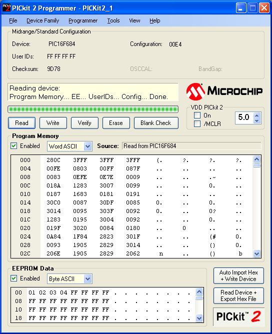
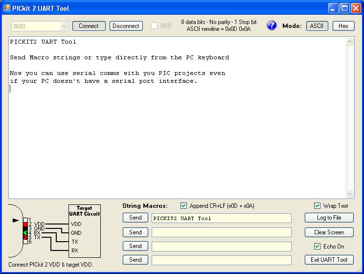
Microchip have now brought out the PICkit2 programmer. It programs a large range of PICs and it certainly covers all the devices you are likely to want to use in a hobby environment and possibly professionally too. It integrates with Microchip's MPLAB IDE application software as well as having its own standalone programmer application. Not only can it program a good range of PICs, it can also program and read EEPROM. Microchip continue to develop the software for the PICkit2 and as new PICs are introduced support is added for them. The PICKit 2 also supports a simple 3 channel logic analyser function and serial terminal interface (handy if your PC doesn't have any RS232 serial ports). Because the PICkit2 uses a USB interface you can connect multiple PICKit programmers to your PC at the same time, use one as a programmer, another as a logic analyser, a third one as a serial port. It really is a very useful development tool.
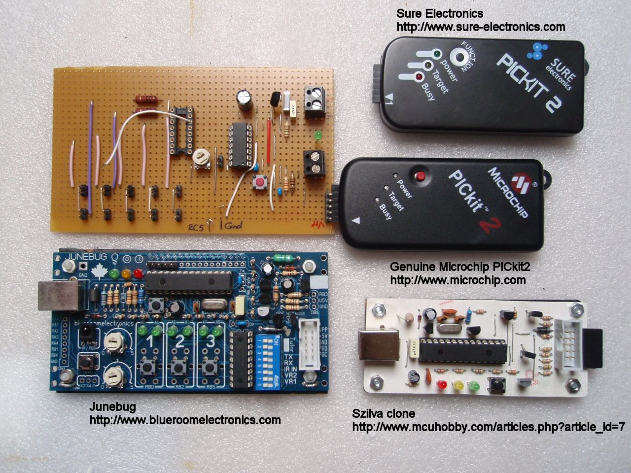
The genuine Microchip part
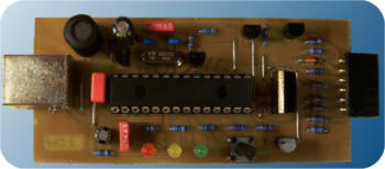
PICKit2 Clones Because of the way the PICkit2 works and the simplicity of its design it is easy to build a clone version of the genuine thing. Most of the clones will only work at 5 volts where the Microchip PICkit2 will support 3.3 volt parts and some of the clones don't support the Programmer-to-go function or EEPROM programming A nice simple PK2 clone is presented on this website http://www.mcuhobby.com/articles.php?article_id=7. I've built two of these and they work really well. One thing to note is the PIC18F2550 used in the circuit needs programming initially with bootloader code so you need access to a programmer to get it working. If you build this, be careful with R4/R6. The component overlay is ambiguous as to which is which so check the schematic then look at the PCB track. Photo of this PK2 clone is shown below left.
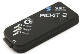
Some other PK2 clones http://www.micros-designs.com.ar/pickit2-clone-5v3-3v/ Sure Electronics This is quite a good clone and comes with USB and ICSP cables. They have a website http://www.sure-electronics.com and they sell through an e-Bay shop Search under MCU Development. I have one of these programmers myself. AU Electronics This company sell some good PICkit2 clones with enhanced features, based in the US/Canada they ship worldwide. Free programmers and software from the Internet I've updated this section as of April 2009. I used to suggest you try the free programmers and software you can find on the Internet. However, the feedback I've had over the last couple of years via the Picprojects website has changed my view. All the queries I get relating to programming firmware from the Picprojects site concern non-microchip programmers. Many of these other programmers either don't support or haven't been updated to fully support newer PICs. Some of them appear to either ignore or require manual intervention to preserve configuration and calibration data. The bottom line is that you really need a lot of practical experience to have a good experience using one. If you're new to PICs and programming you're unlikely to have that level of experience so you'll end up struggling, frustrated and demoralised; not a good start. The popularity of the PIC owes a lot to the availability of free programming hardware and software and I recognise that but times have moved on. With the low cost of the PICkit2 I really see no reason not to buy one. I use them and I advise you to do the same. Microchip now have two versions of the PICkit programmer with the introduction of the PICkit3. This at first appears to supersede the PICkit2 however they haven't stopped selling the PICkit2 and currently the support and application features for the PICkit3 are not as good as the original PICkit2. The PICKit3 is also more expensive to buy. As well as full support for the PICkit3 in MPLAB, Microchip have now brought out a standalone application for the PICkit3, similar to that for the PICkit2 but not as fully featured offering only basic standalone programming without the serial terminal and logic analyser applications that you get with the PICkit2. Therefore if you're just using base line and midrange PICs (which includes those PICs used on the Picprojects website) I would still recommend you buy the PICkit2 and not the PICkit3. The PICkit2 also supports the new enhanced midrange 12F1xxx and 16F1xxx PICs For more information on these two
programmers and a simple ICSP programming adapter check out my You can get C compliers, Basic compilers and Assemblers for the PIC. Some are free, some you pay for and yet others you pay even more for, there is even a compiler language called JAL written just for the PIC and it's free. Of course, you can just program in straight assembler and Microchip provide free IDE software for code development and simulation/debugging. A few links for starters are here, there's a lot, lot more out there, Google for them.
Although the Microchip MPLAB IDE has a software simulator it's not easy or in some case possible to emulate interrupts and some of the hardware devices such as the USART. I've found a really great PIC simulator that you can get here http://www.oshonsoft.com/. Download a time-limited version for free and try for yourself. The cost of the personal edition is only about £12 and I've found it a really useful application. Tutorials Hundreds of PIC tutorial web sites out there, many of them are rubbish, out-of-date or written by people who know less than you do already so be careful which one you PIC (pun intended). However, it's not all bad and two that I think are worth a spending some time looking at are:
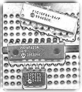
And don't forget the Help files in MPLAB. These already contain many answers to questions you may have so it's worth having a look through them. Forums Forums are good on two counts; if you just lurk on a forum you can pick up lots of useful tips and helpful information. If you have a specific question, they're a good place to get the answer. When asking a question on a forum word your question so it is concise and clear, read back what you write before posting and don't ask a question that's already been answered previously. Occasionally you can pick up some good deals on PICs on E-bay, just browse to Business, Office & Industrial > Electronic Components then search for the key word PIC. I also sell some of the PICs used in projects on this website from the Picprojects eShop, both pre-programmed with the project code and also new blank parts. There's a lot of information and reference to the 16F84 PIC chip. This chip is an old PIC dating from the 90's. You are much better off going for one of the newer PIC's like the 16F627A/628A or 12F675. The 16F627A is pin compatible with the 16F84 but has a lot more functionality, including internal 4Mhz oscillator so you don't need an external crystal or resonator. The other reason for going with these newer PICs is that the arrangement of their special function registers is standardised so it's easier to port code from one chip to another. In addition the program FLASH memory is now rated for much higher write/erase cycling than the 16F84. Two even newer PICs that are worth considering for any new projects are the 12F683, which is backward compatible with the 12F675 but has additional features including 2K program memory and 8Mhz internal oscillator. Then there's the 16F88 which has 4K program memory, 8Mhz internal oscillator and the ability to self-program along with lots of other features. I also like the 16F690, 20 pin device, all the features of the 16F88 except self-program and cheaper. It's worth looking over the datasheet for these devices if you're planning a new project. From 2010 Microchip intoduced a new range of 14-bit 'Enhanced Mid-range' PICs such as the 12F1822, 16F1823 and 16F1827. These are cheaper, loaded with peripheral devices and have extra instructions and memory handling so for any new project these are definitely worth looking at. This document from Microchip is a good briefing of the features of these new PICs. Finally, the newer parts are generally cheaper to buy which is as good a reason as any to use them. The Microchip PIC microcontrollers use a Harvard architecture where code and data memory are separate, unlike the von Neumann architecture used on processors such as the Intel Pentium. The device uses a RISC instruction set with just 35 instructions. All instructions execute in one instruction cycle except for those that modify the program counter such as conditional branches, and goto's which always need two cycles. Despite this alternative architecture, it is very easy to work with. I've had quite a lot of experience with the 6502 processor from the early 1980's (used in the Apple II and BBC Micro among many). Although the 6502 had some better test and branch functions, it had only two internal registers so I've found the limited instruction set on the PIC quite easy to adapt to. In addition, the instructions the PIC has, particularly for bit testing and manipulation, are well suited to its intended applications. PIC Instruction Set Before you start using a PIC microcontroller you'll need to know all about it. You should download the datasheet and while you don't need to read it cover to cover, it's the first place your should turn to when you're not sure about something, or things aren't working as you expected. You can download datasheets from the Microchip website and while your there, take a look through the Application Notes, there's lots of interesting and useful information to be found in them. For full details of the Microchip Mid-Range MCU family check out this data sheet (it's big, 3Mb PDF) from Microchips website. |