|
|
Internal
Oscillator Recalibration Utility
for PIC 12F629 & 12F675
|
 |
Description
The PIC 12F629 and
12F675 devices have an internal 4Mhz oscillator that enables the
devices to be used without an external crystal or RC network.
This frees up one or two pins for I/O use and allows the device to
be built into minimum component count designs.
The internal oscillator needs to be
calibrated and this is achieved by reading a factory programmed
calibration setting and writing it into the OSCCAL register during
initialisation of the device by the application software.
The calibration word is located at the
last address in the user program memory area, address 0x3FF.
It is in the form of a RETLW instruction and the user code should
include a CALL 0x3FF instruction which will return with the
calibration setting in the W register. This can then be written into
the OSSCAL register.
Problems arise if by accident or
otherwise, the program memory at address 0x3FF is erased or over
written. Since the calibration value is unique to each
individual PIC there is no way to know what it was, but it is
possible to recover it by recalibrating against a known frequency.
That's where this software and circuit
come into their own. Load a PIC with the code on this page and
drop it into the circuit described here and within a couple of
seconds it will provide a new calibration value to ensure the
internal oscillator runs within 1% of 4Mhz.
PICkit 2 update
If you have a PICkit 2 programmer, get
version 2.50 (or later) software from the Microchip
website. This includes a menu option to recalibrate and
reprogram the OSSCAL setting in one operation. This project
page remains here for those who don't have access to a PICkit2.
How it works
In order to calibrate
the internal oscillator a known reference frequency is needed.
Fortunately we don't need signal generators or calibrated test
equipment for this. In fact an accurate reference is available from
the AC utility electric supply. In most parts of the World the
utility electricity
supply is generated at a frequency of either 50 or 60Hz (many digital clocks take advantage of this fact to keep time)
Using almost any
transformer (or Wall Wart) with a 6 to 12 volt RMS AC output we can obtain an accurate
reference source to calibrate the PICs oscillator against.
Schematics,
Construction, and Code
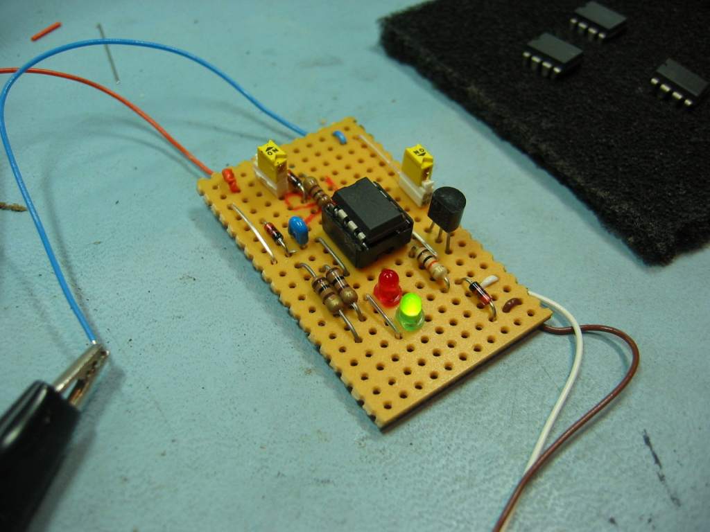
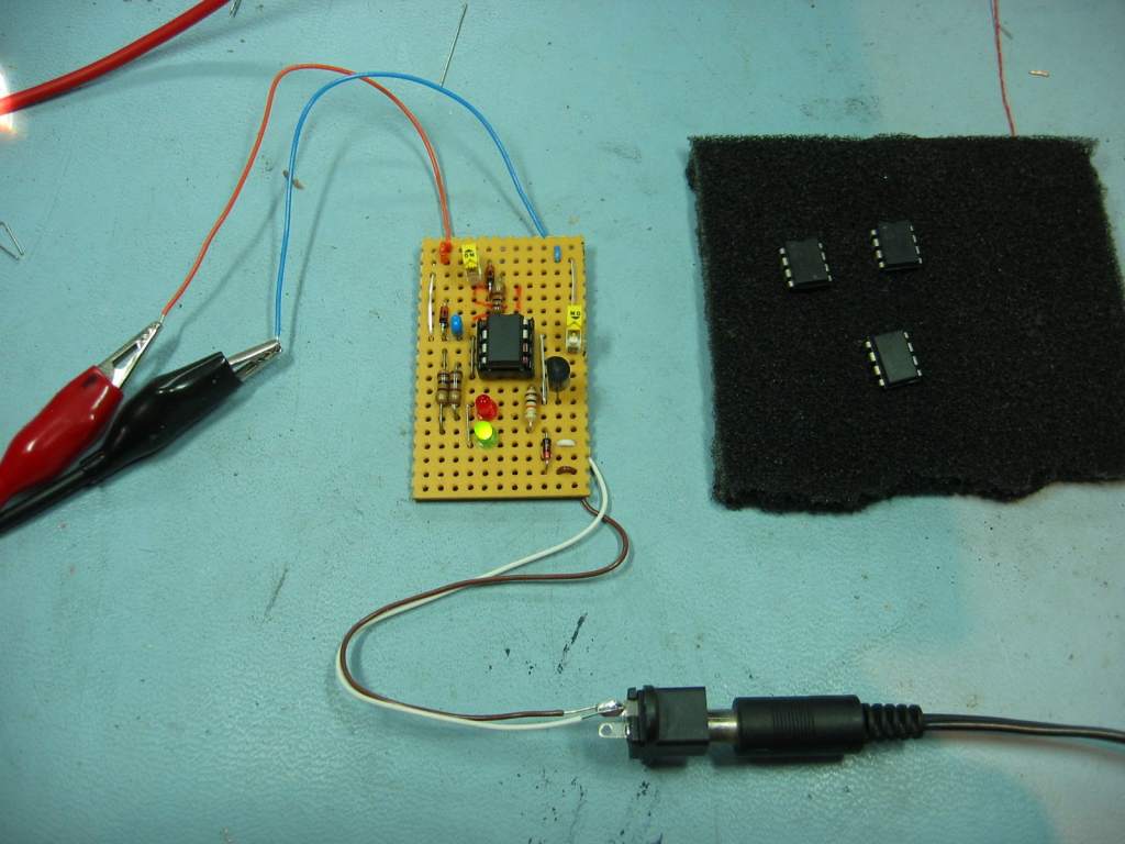
So let's get on with
it. Construct the circuit shown below using a piece of strip
or pad board, or just hook it up on a solderless breadboard.
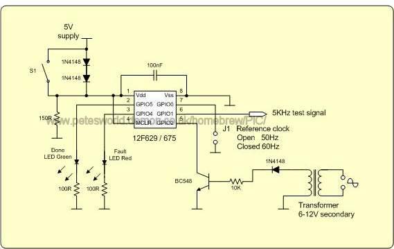
The frequency of the
internal oscillator in the PIC varies with both changes in temperature
and supply voltage. As the supply voltage increases the frequency
decreases slightly. When switch S1 is open the 5 volt supply to
the PIC is dropped across the two diodes to about 3.4 volts. With
S1 closed, the PIC operates at 5 volts. Microchip calibrate parts
at 3.5 Volts / 25oC. With this circuit you have the
option to calibrate at either 3.4 volts or 5 volts. Unless you have
a specific reason not to, it is advisable to recalibrate the PIC
using the S1 open (3.4 volt) setting.
S1 open -
calibration takes place at 3.4 Volts
S1 closed - calibration takes place at 5 Volts
 S1 is not a power on/off switch
The two 1N4148 diodes
provide the voltage drop and the 150R resistor draws sufficient current
to ensure the voltage across the diodes remains stable.
The 100nF decoupling
capacitor should be placed as close as possible to the power pins (1 and
8) of the PIC.
The reference signal is
supplied using the BC548 transistor, 10K resistor, 1N4148 diode and
transformer. You can use any general purpose NPN transistor here
as it is not critical. The transformer is also not too critical
but should output between 6 and 12 volts AC RMS.
It is important that input
to the transistor is an AC signal. Don't use DC, not even unfiltered
DC (no smoothing capacitor)
 DO NOT UNDER ANY
CIRCUMSTANCES CONNECT THIS CIRCUIT DIRECTLY TO THE UTILITY POWER DO NOT UNDER ANY
CIRCUMSTANCES CONNECT THIS CIRCUIT DIRECTLY TO THE UTILITY POWER
PIC code for recalibration
Next you need to
program the PIC to be recalibrated with the code below. The same code will work with
both the PIC 12F629 and 12F675 devices. Download it now and and program it into the PIC to be calibrated.
Download HEX code  (for use
with either 12F629 or 12F675) (for use
with either 12F629 or 12F675)
Download MPLAB-X project
Once you have
successfully recalibrated the PIC and read back the new calibration
value you can reprogram the PIC with your own application code.
This software is only needed to calculate the new calibration value,
it doesn't need to remain in the PIC afterwards. (someone will ask
believe me!)
Running the calibration
-
Close J1 if the
utility power in your area is generated at 60Hz and leave it open if
it is 50Hz. Make sure you get this right or the calibration
will either fail or worse, be incorrect.
J1 Open - AC Utility Power Supply 50Hz
J1 Closed - AC Utility Power Supply 60Hz
-
The AC reference signal
should be present before powering up the PIC under calibration to ensure
the signal is stable and running.
-
Insert the PIC into the
socket, open switch S1 and apply 5 volts to the circuit.
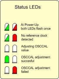
- When the PIC
starts both the LEDs will blink once.
- If no reference signal is detected
on GP2 (pin 5) the fault LED will light and the 'done' LED will
blink until a signal is detected. (If this happens, turn the
power to the PIC off and on to ensure it calibrates correctly)
- During the calibration process
both LEDs are off. The calibration will take less than 5
seconds to complete.
- If the calibration failed the
red LED will come on and the code will halt.
- If the calibration is
successful the green ' done' LED comes on and a 5Khz test signal
will be generated on GPIO1. If you have a frequency meter
handy you can use this to verify the calibration.
- Once calibration is complete,
you can open and close switch S1 while monitoring the 5KHz test
signal to see the change in frequency vs. supply voltage.
- Turn the power off, remove the PIC from the test circuit and
put it in your programmer. Now read back the PIC and
inspect the contents of the EEPROM memory
-
When you read back the
EEPROM it will contain one of three pairs of values in addresses
0x00 and 0x01 as follows:
 EEPROM addresses
0x00 and 0x01 contain 0xFF
EEPROM addresses
0x00 and 0x01 contain 0xFF
then the code failed to run correctly.
EEPROM addresses
0x00 and 0x01 contain 0x00
then the code did run but it has failed
to set the calibration word correctly (finished with fault LED on).
Check that your reference clock is running at the correct frequency,
J1 is set correctly and then retry.
 EEPROM address
0x00 contains 0x34 and address 0x01 contains 0xNN where NN is the
new calibration setting.
EEPROM address
0x00 contains 0x34 and address 0x01 contains 0xNN where NN is the
new calibration setting.
then the code ran successfully (finished with 'done'
LED on) and calibrated the OSCCAL value correctly.
Use the 0xNN value in address 0x01 for the calibration
memory.
|
 |
Update:
It has been brought to my attention
that some programmers / software raise the VDD supply before VPP.
This allows the code to start running before the PIC enters
programming mode prior to reading back the EEPROM. If the
green LED indicates a successful calibration but on reading the
EEPROM back you find it contains 0xFF in addresses 0x00 and 0x01
then your programmer is doing this.
If you have this problem you can
download a modified version of the original program below.
This version doesn't initialise the EEPROM on startup so the
calibration data doesn't get cleared when the PIC is read back in
the programmer. Only use it if you have this problem.
Download HEX code (modified
version with no EEPROM initalisation)
Using the new
calibration word
-
IMPORTANT: This code
will calculate the correct calibration word but it can't
save it back into the PICs program memory - You must do this
manually using your PIC programmer.
-
If you
calibrate a PIC where you still know the factory calibration
value you may find the value produced by this circuit is
slightly different from the original factory value.
This is normal and is down to differences in supply voltage
and temperature. You can verify the 5Khz test
signal on GP1 with a frequency meter after calibration is
complete and it should be within 1% of 5Khz.
|
If calibration
completes successfully, remove the PIC and place it back into your
programmer. Read back the data from the PICs EEPROM memory
(not program memory) where the newly calculated value has been
saved. (see example below)
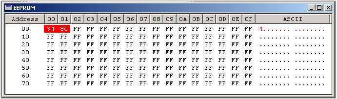
Address 0x00 will
contain 0x34 and address 0x01 will contain the calibration value.
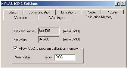
It is this value that needs to be written back to program memory
location 0x3FF using a RETLW instruction. Some
programmer software will allow you to enter the calibration value
and program it back into the device for you. If your
programmer doesn't do this then you need to put a RETLW 0xNN
instruction at address 0x3FF where 'NN' is the hex calibration value
read from the EEPROM.

Contact us:

|