This project is an
update to the original RGB LED
PWM Driver. The new version allows the
use of either 5mm LEDs or the square bodied
Superflux / Piranah style LEDs. The circuit
now uses bipolar transistors rather than MOSFETs
which make it more suitable for novice constructors
and for the first time this project is available as
a kit with all parts required to assemble the PCB
including the superflux LEDs. (power supply not
included)
Full schematic and
construction details are shown on this page, as well
as the firmware download for those who want to
create their own effects or build their own version
from the schematic. If you're not into
programming the kit includes a PIC microcontroller
pre-programmed with the firmware and a number of
mood lighting effects.
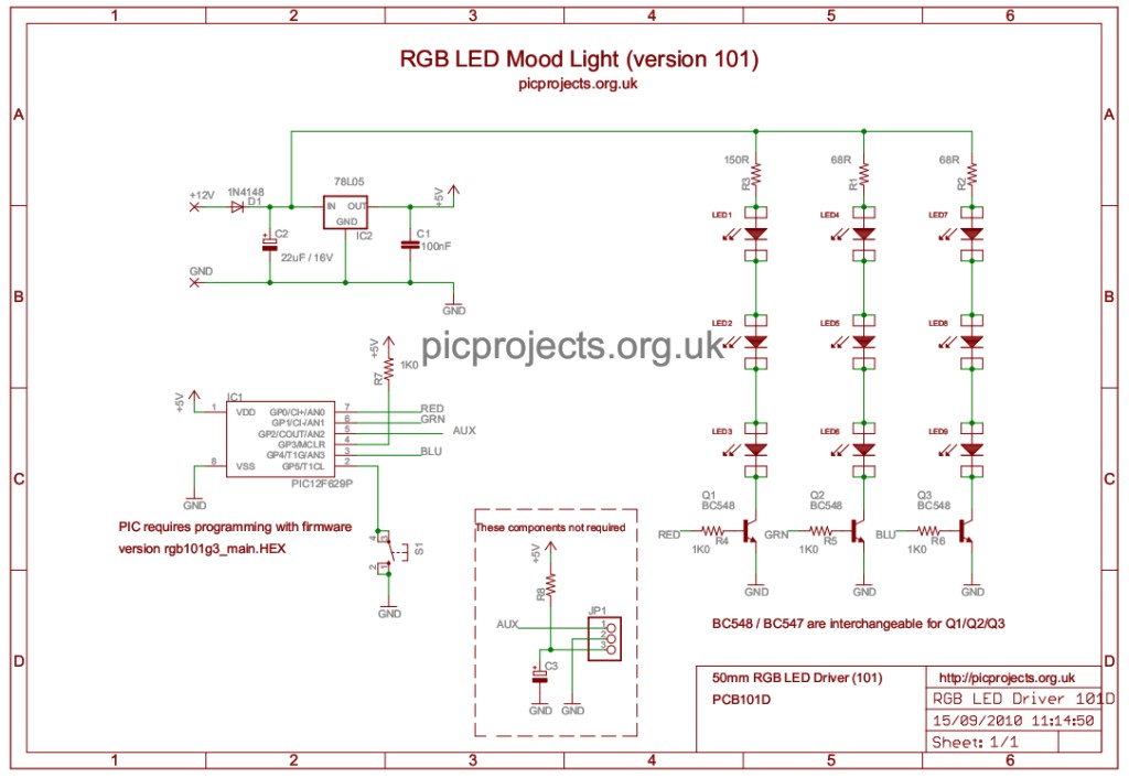
The circuit itself is
fairly straightforward. Diode D1 provides
reverse polarity protection for the board in case
the power supply is connected backwards. C1/C2
and IC2 take the incoming 12 volt supply and provide
a regulated 5 volt supply required by the PIC
microcontroller.
The red, green and blue
LEDs are arranged in three parallel strings of three
LEDs. Resistors R1, 2 and 3 limit the current
through the LEDs to a safe value when using a 12
volt power supply. The low side of each LED string
connects to a BC547 NPN transistor which is used to
switch the LEDs on and off. These transistors
are in turn controlled by the PIC microcontroller
which drives each of the red, green and blue channel
transistors with a PWM signal to control the average
brightness of the LEDs. Switch S1 is used to
select different effect sequences. The
firmware program running on the PIC microcontroller
is the smart part of the circuit and determines what
colours are generated and how they fade from one
colour to the next.
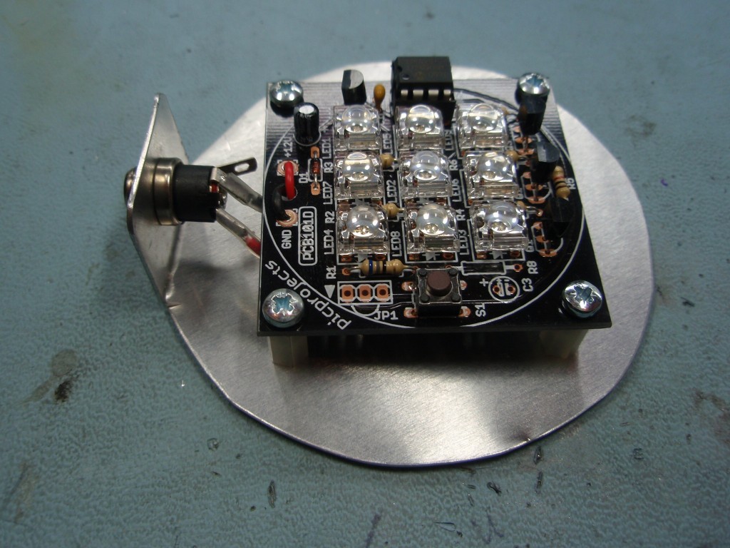
The three colours of
LEDs are positioned on the PCB in an irregular
arrangement to improve the colour mixing effect when
placed behind / inside a diffuser such as a frosted
glass globe.
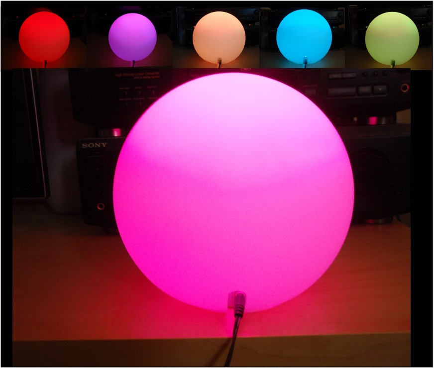
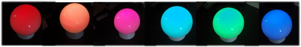
The controller uses
(RGB) Red, Green and Blue high brightness LEDs that
are pulse width modulated (PWM) to vary the
intensity of each colour LED. This allows
effectively any colour to be generated with rapid
changing strobe effects, fast and slow colour fades
as well as static colours. The data used
to set and change the colours is held in an easy to
edit file so if you don't like the sequences
provided with it, you can modify the sequence data
include file yourself and reprogram with your own
sequences. (you will need a PIC programmer and
some practical knowledge of microcontrollers and
programming if you want to do this.)
The
PCB supplied with the kit is professionally
manufactured thru-plated with solder mask
top and bottom and screen print overlay on
FR4 laminate with RoHS finish.
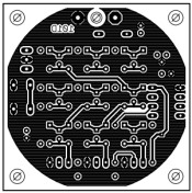
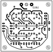
If
you want to etch your own PCB you can use
the artwork above. Unless you are able
to thru-plate your own PCB you will need to
solder component leads top and bottom where
required. Also look for the single via on
the board that will need to be wired
through.
The
ready made PCB supplied in the kit has
through plated holes so this does not apply.
The
information in this section is relevant whether
you are assembling from the kit or sourcing
everything yourself so please take the time to
read through this section and refer back during
assembly. This section is written so that
even someone with little knowledge of
electronics can successfully assemble the board;
for those with more experience there is still
useful and relevant information so please stick
with it.
Photo.1
Photo.2
Photo.3
Photo.4
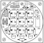
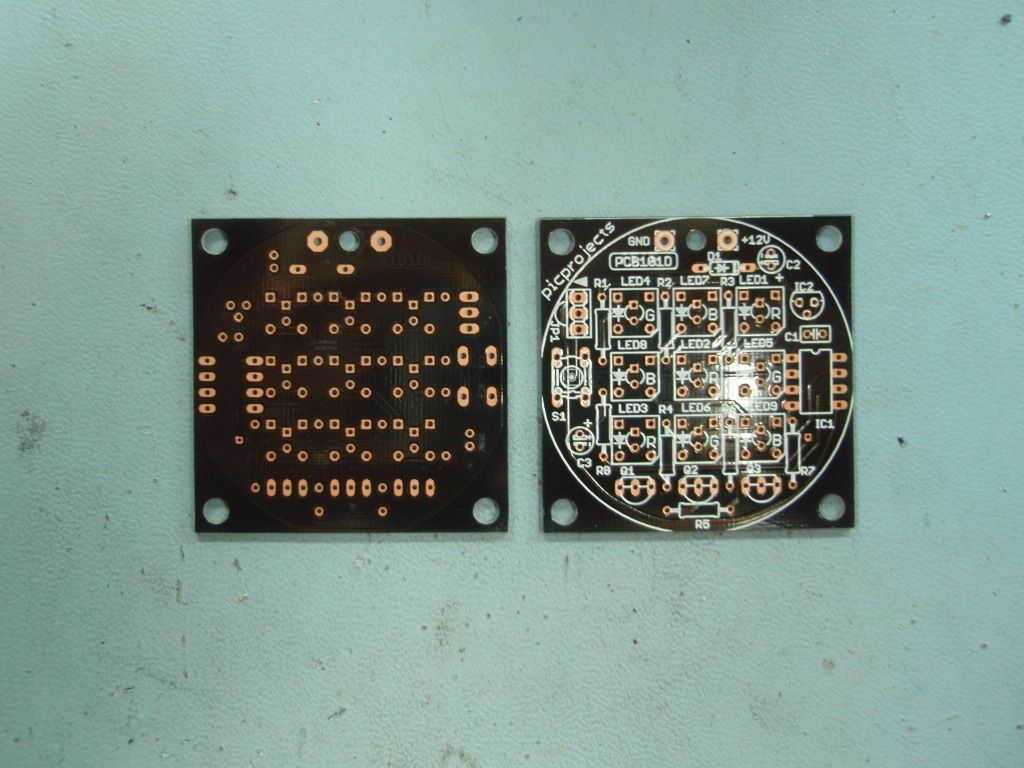
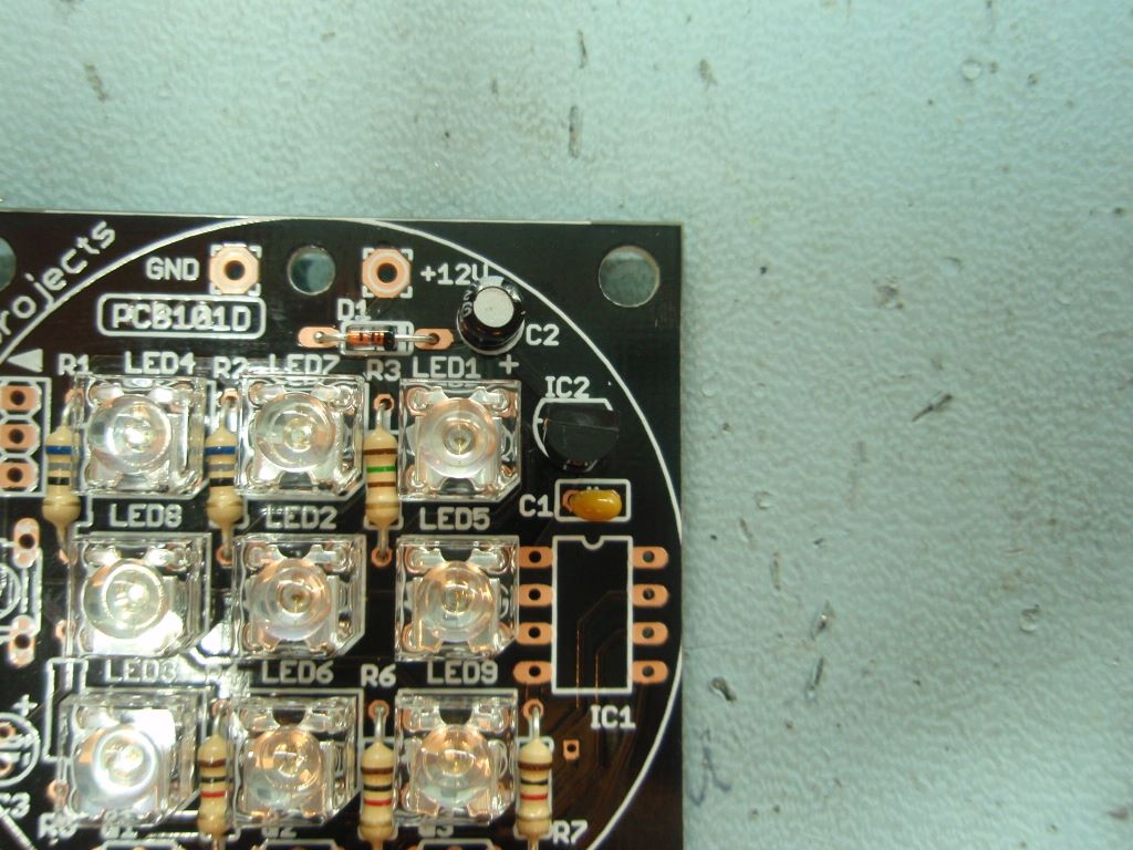
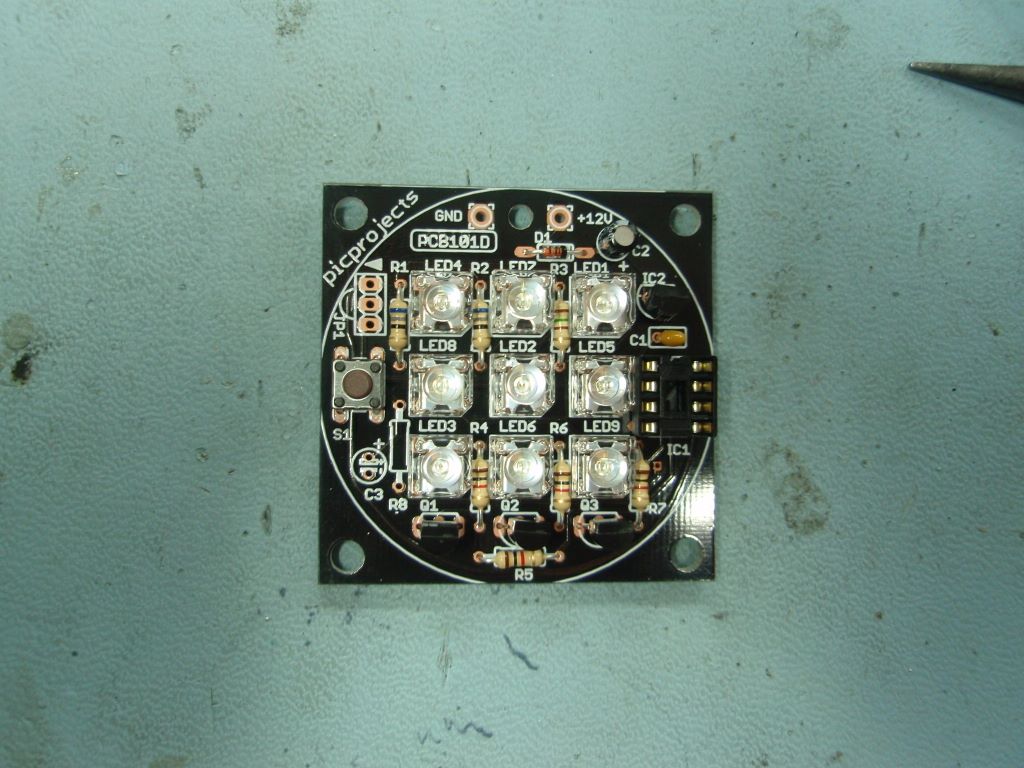
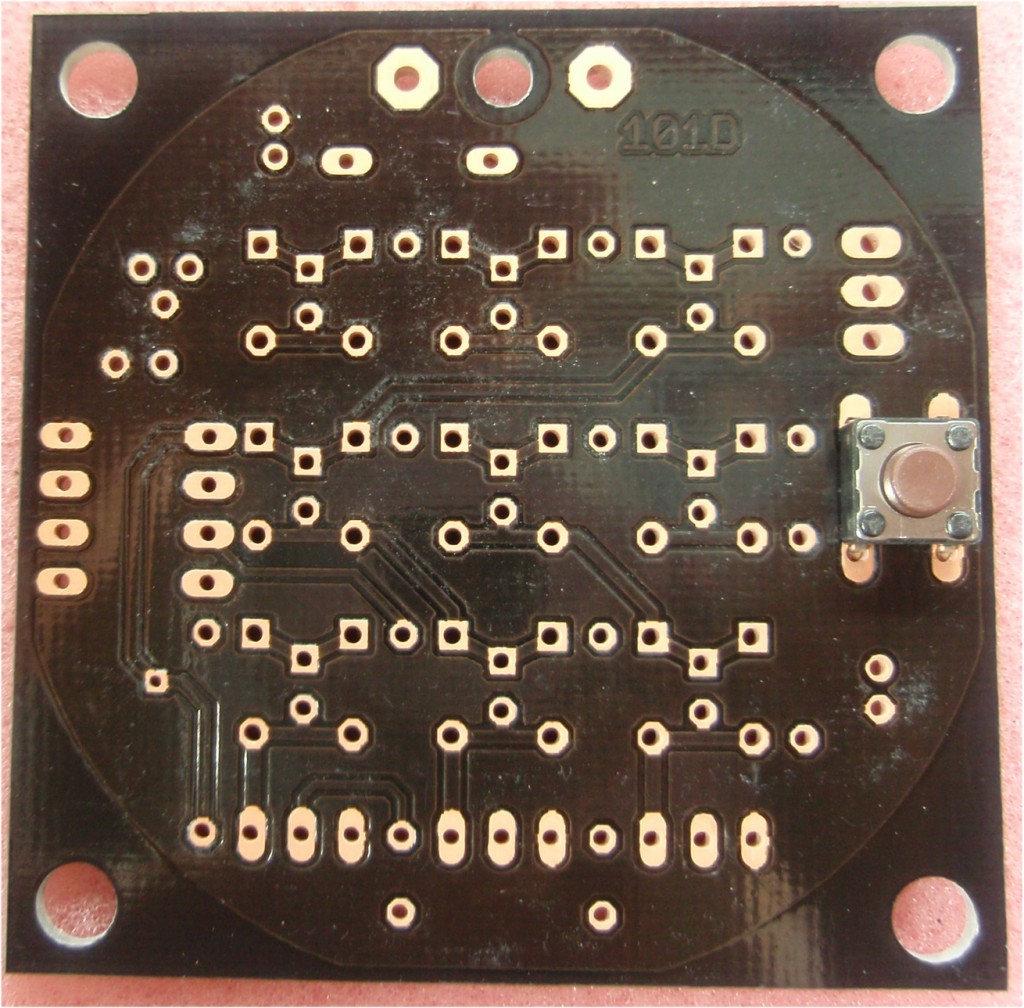
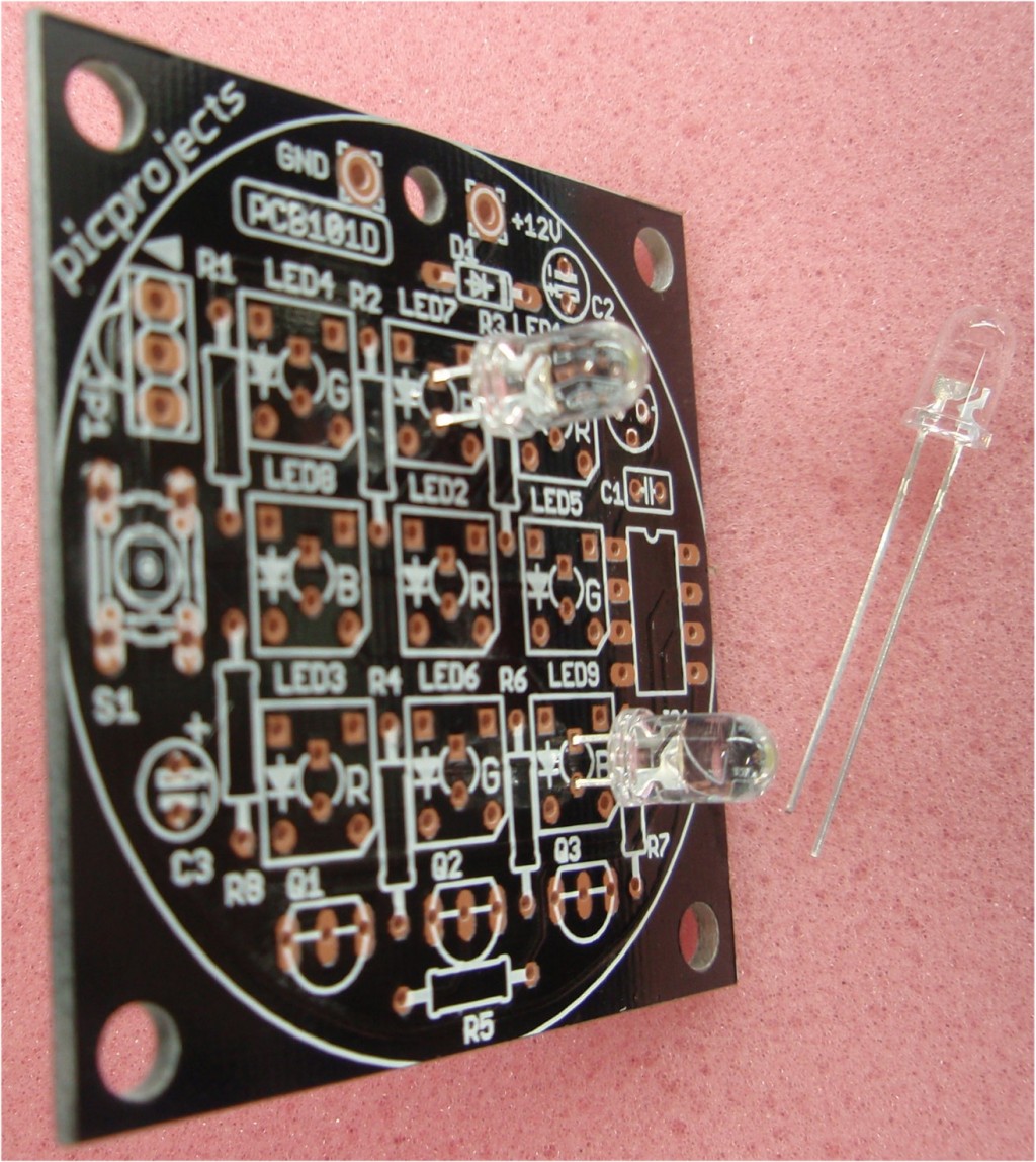
Photo. 1
The bare PCB.
The component side has a white component
overlay silk screened onto the board which
should be used as a reference when
installing the components.
Note:
Components JP1, R8 and C3 are not used
with this project and are not supplied
in the kit #101F.
Now you want to know why don't you? Read
this
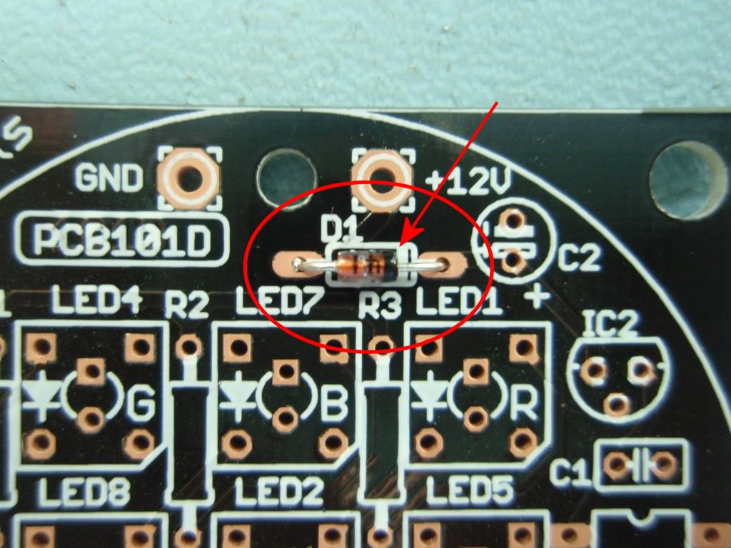
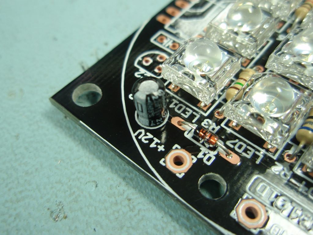
Photo. 2
Start by
installing the 1N4148 diode D1 in the
position shown. Note the black band
around one end of the diode. This
must be installed in the direction shown
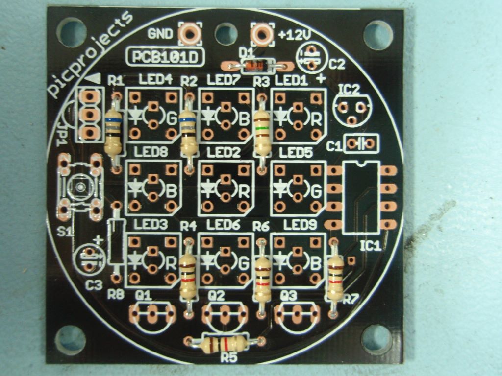
Photo. 3
Install all
the resistors. The coloured bands
denote the resistor value. It
doesn't matter which way round you fit
them but you must make sure the right
value resistors are installed at the
correct locations.
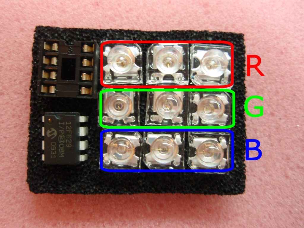
The
LEDs are shipped in anti-static foam
along with the PIC16F629
microcontroller and IC socket.
The red, green and blue LEDs appear
physically identical when not
operating. In order to
identify them for assembly they are
placed in the anti-static foam in
three rows as shown in photo.
4
Please DO
NOT REMOVE the LEDs until you
are ready to fit them and then do so
one LED at a time. If you get
the LEDs mixed up and solder one into
the wrong position it is difficult to
unsolder them without damaging the PCB
and/or LED.
Photo.5
Photo.6
Photo.7
Photo.8
Photo.
5
Now install
the three RED
LEDs in the locations marked 'R' on the
PCB overlay. One corner of the LEDs
plastic body is cut-away. You must
install the LED so that this corner
corresponds to the marking on the PCB
overlay. Also make sure to keep the
LED firmly pressed against the PCB while
soldering in place so it doesn't finish at
some odd angle.
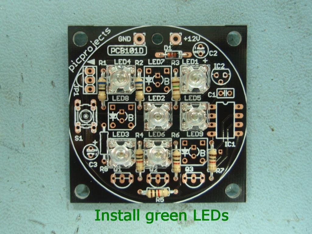
Photo. 6
Now install
the three GREEN
LEDs in the locations marked 'G' on the
PCB overlay. One corner of the LEDs
plastic body is cut-away. You must
install the LED so that this corner
corresponds to the marking on the PCB
overlay.
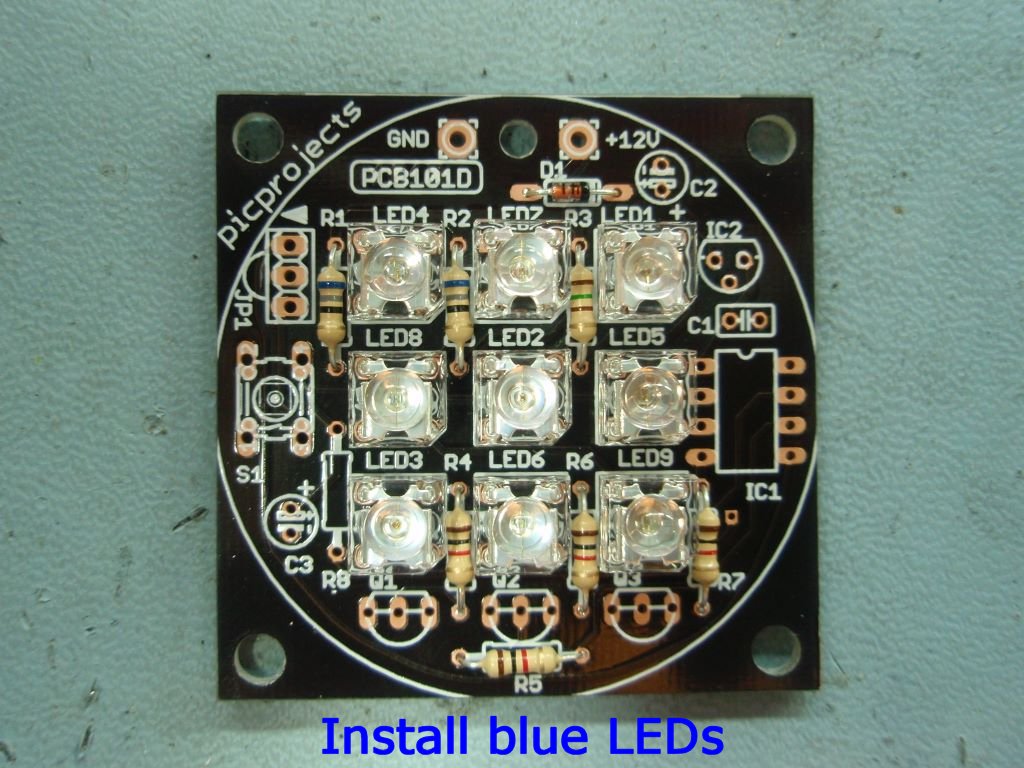
Photo. 7
Now install
the three BLUE
LEDs in the locations marked 'B' on the
PCB overlay. One corner of the LEDs
plastic body is cut-away. You must
install the LED so that this corner
corresponds to the marking on the PCB
overlay.
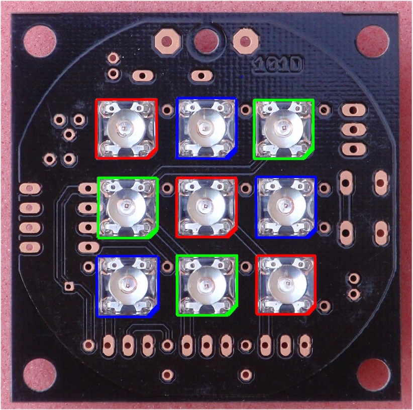
Option to
install LEDs on the back side of
the PCB
Depending
on your application for the mood
light you may want to mount the
LEDs on the back side of the PCB
so you don't see the other
components.
If
you do this you need to be careful
to fit them in the correct
location and orientation since
there is no overlay on the back
side.
The
photo (right) shows where to fit
them and the correct
orientation. Since the holes
in the PCB are plated through you
will solder the leads on the top
side of the board.
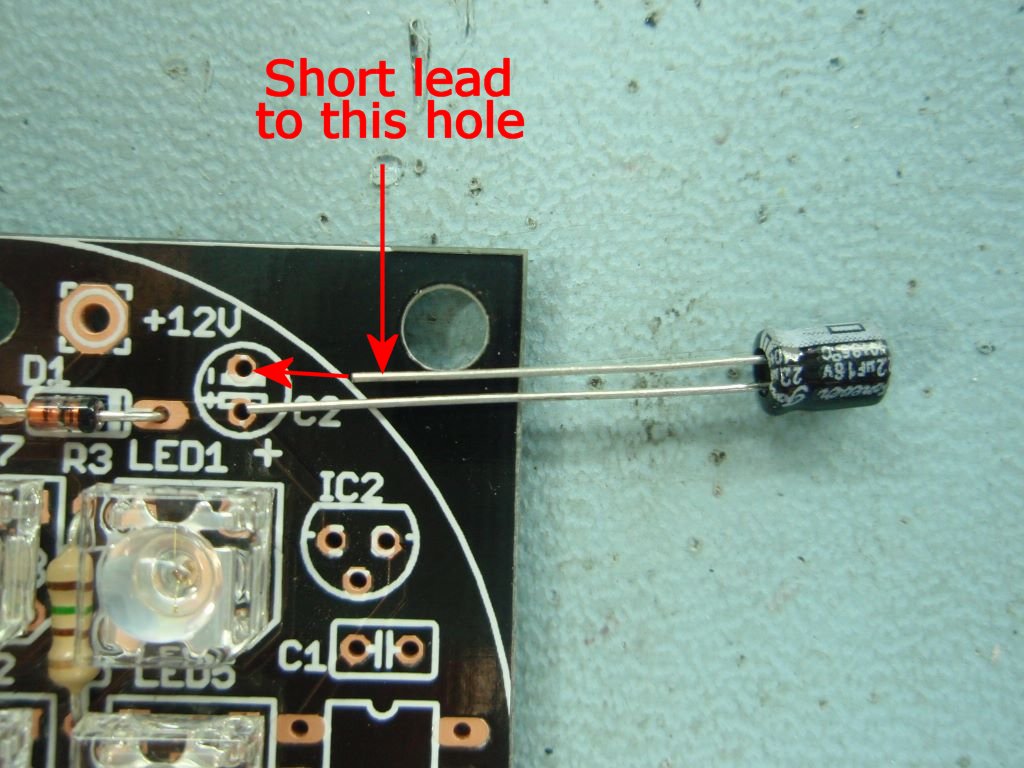
Photo. 8/9
Install the
22µF capacitor C2. One
lead is shorter than the other. You
must install the short lead into the hole
nearest the edge of the PCB as shown.
Photo.9
Photo.10
Photo.11
Photo.12
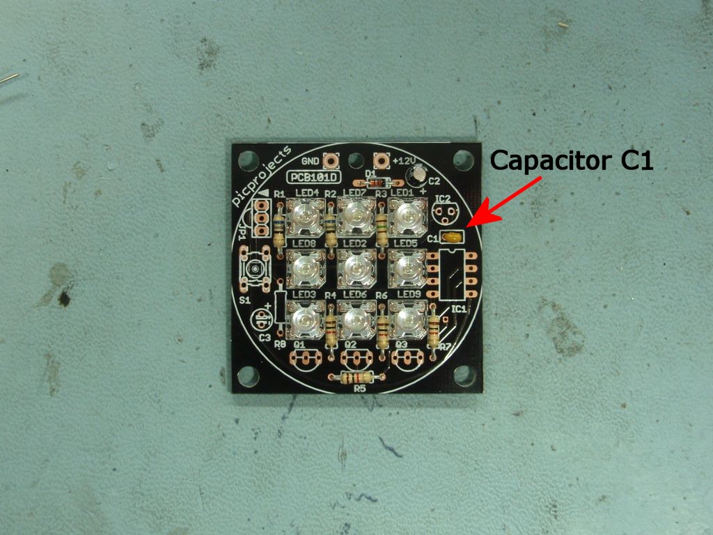
Photo. 10
Install the
100nF capacitor C1. This can be
fitted either way round.
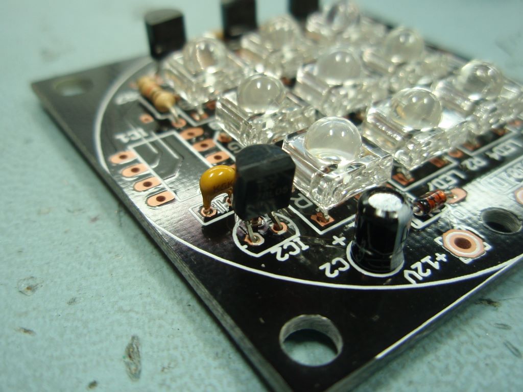
Photo.
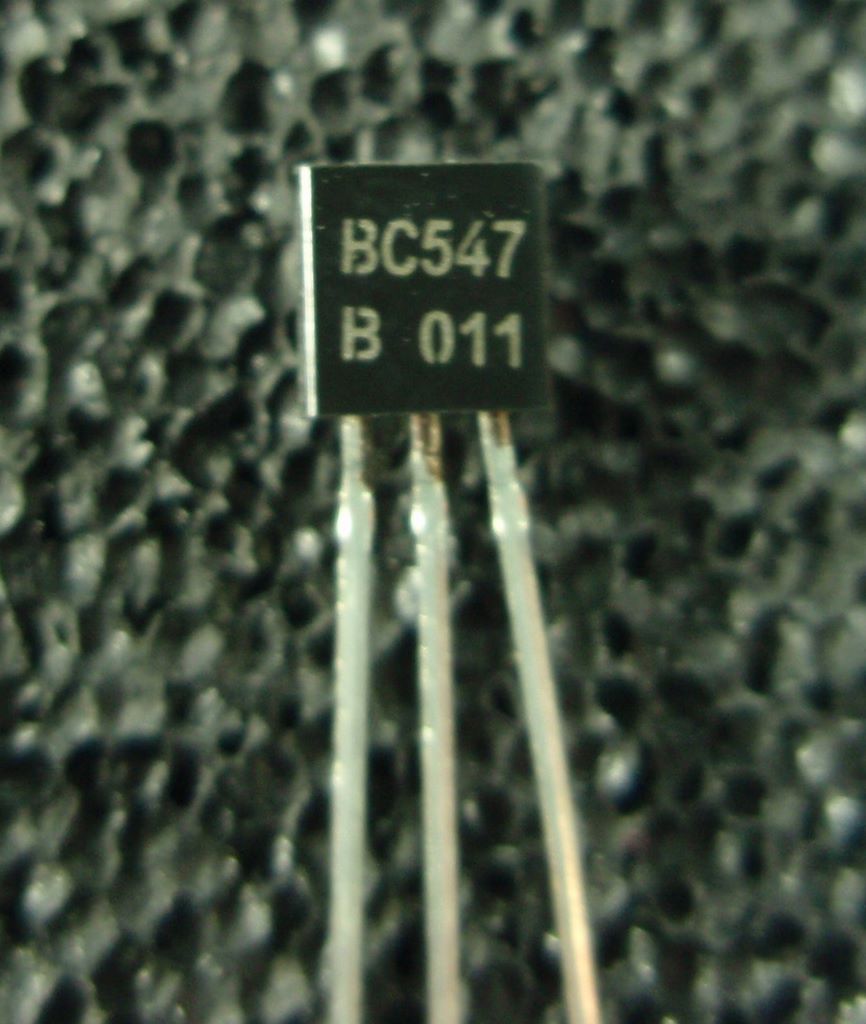
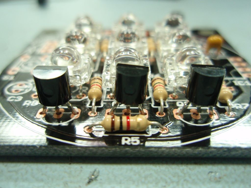
11/12
Next install
the three BC547 transistors Q1,2,3.
These look physically similar to IC2 so
make sure you check the laser-etched
marking on the body of the part (photo.
11). The transistors must be
installed the correct way round. Align the
body to match the PCB overlay.
BC548 transistors may also be used for
Q1,2,3 and are interchangeable with the
BC547 part.
Photo.13
Photo.14
Photo.15
Photo.16
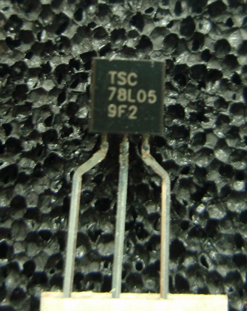
Photo.
13/14/15
Now install
the 78L05 voltage regulator, IC2.
The wire leads on this part may need to be
realigned to go through the holes on the
PCB, carefully bend them using flat
nose pliers. Again, this part needs
to be fitted the correct way round.
Ensure the body is aligned to match the
PCB overlay.
Photo.
16/17
Install the 8
pin socket for IC1. Note the small
notch at one end of the socket. This
should be aligned with the marking on the
PCB overlay.
Also install
switch S1 into its position on the
PCB. You may need to push down
firmly and evenly to get the switch to
seat into the holes in the PCB.
Option
to locate S1 on back side of the
PCB
Depending on your application
you may want to fit switch S1 on
the reverse side of the PCB.
If so, simply fit it on the back
of the PCB as shown and solder in
place.
You
may also use a pair of short wires
(up to 200mm / 7 inches) if you
want the switch located off the
PCB, for example on the outside of
a case.
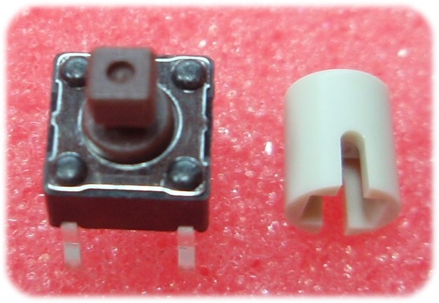
Kit #101F
shipped after 14/12/2010 will contain a
square button switch and round button
cap as shown right. The round
button clips onto the top of the
switch. The switch can be used
without the button if you choose.
Photo.17
Photo.18
Photo.19
Photo.20
Photo.18
Before applying power to the
board for the first time, check the
underside of the PCB for solder bridges,
bad joints and bits of component lead
off-cuts that may have stuck to the board.
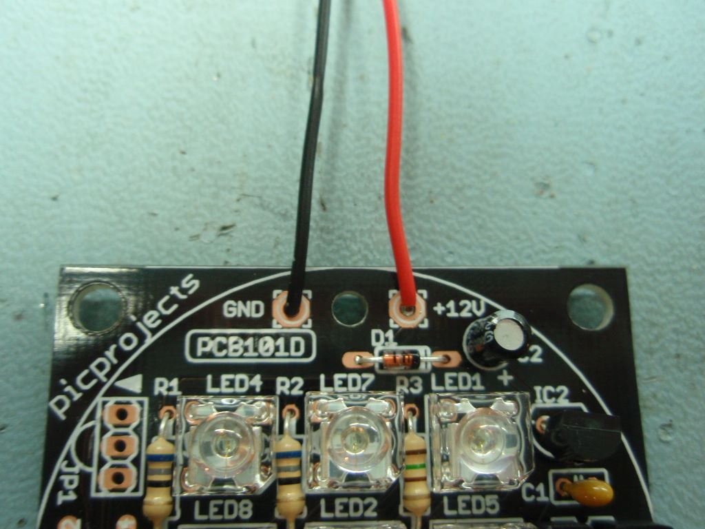
Connect the
red and black wires for the power
connection to the board. The board
requires a 12 volt regulated power supply
input of at least 200mA. See the
section here for more information on the Power
Supply Requirements
The board has
reverse polarity protection so it
shouldn't be damaged if the power supply
is connected the wrong way round,
however it won't operate unless the
power is connected correctly.
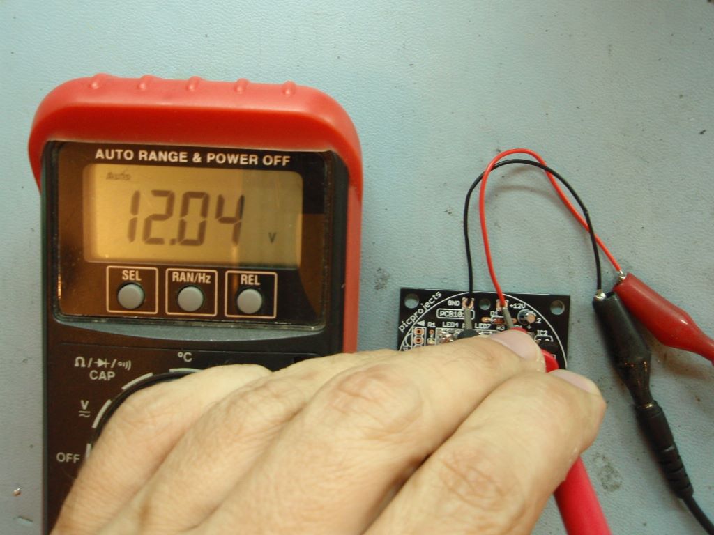
Photo.
19/20
You don't
have to check the voltages to the board
however, if you have a multimeter to hand
it is advisable to have a quick check
before installing the PIC microcontroller
into the IC1 socket.
Check the 12
volt supply to the board. This should be
between 11.8 and 12.8 volts
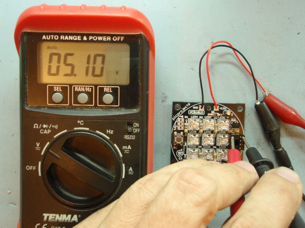
Check the 5
volt supply at pins 1 and 8 of the IC1
socket (photo 20). The voltage
should be between 4.75 and 5.25 volts.
If either of
the measured voltages are outside the
ranges above you need to investigate the
cause before continuing.
Photo.21
Photo.22
Photo.23
Photo.24
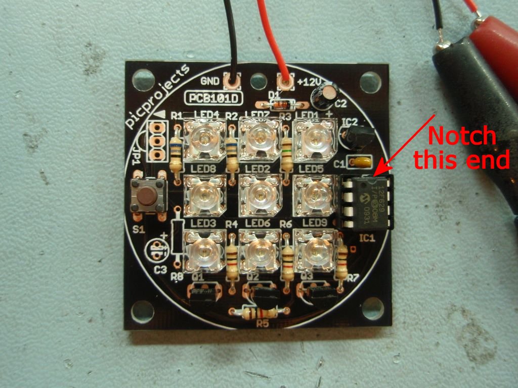
Photo. 21
IMPORTANT.
Before continuing make sure you have
disconnected the power supply to the PCB.
With the
power disconnected you should now install
the PIC microcontroller into the IC1
socket. The PIC has a small
notch or indent at one end. This
should be located towards Capacitor C1 as
shown.
Photo. 22
Take the two
wires connecting power to the board and
pass them through the hole in the PCB as
shown. This acts as a strain relief
for the wires.
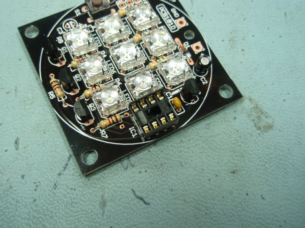
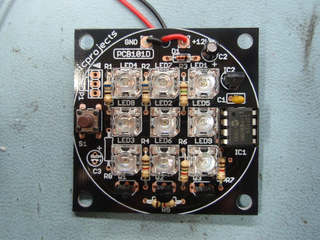
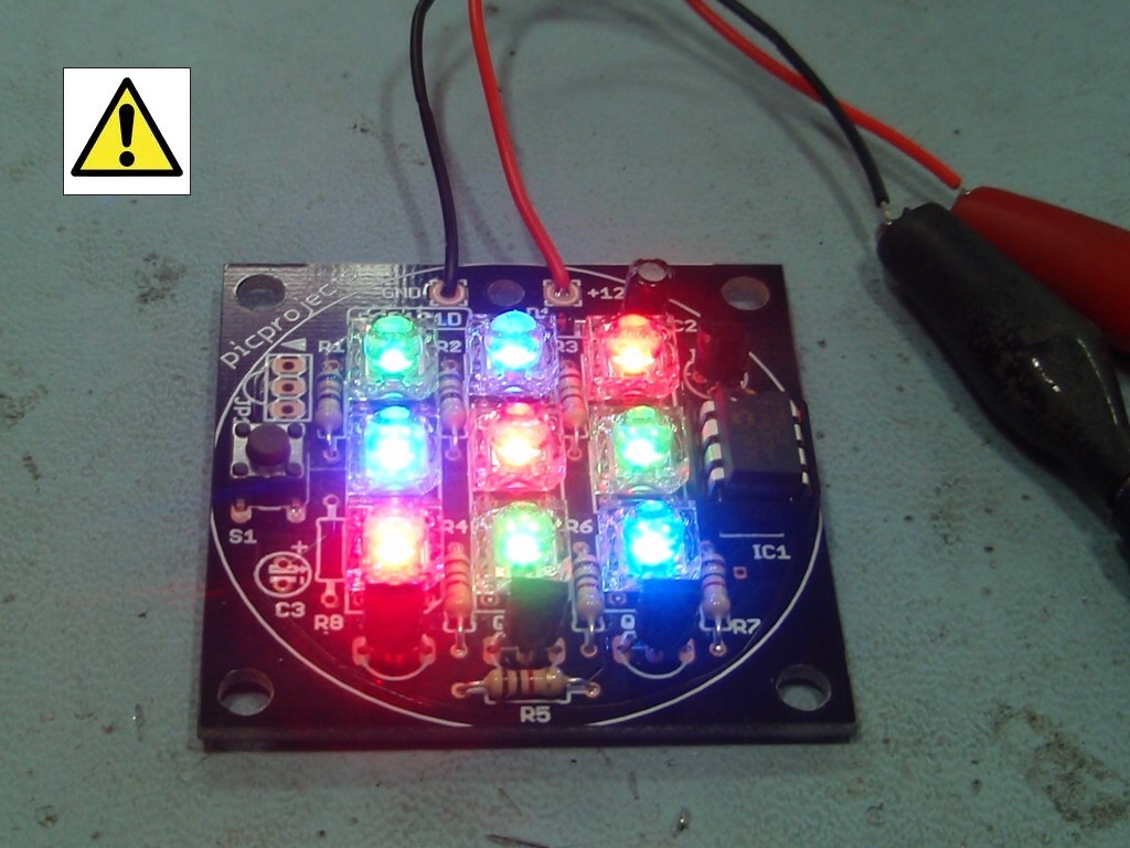
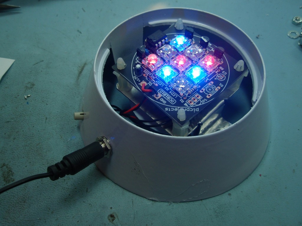
Photo. 23
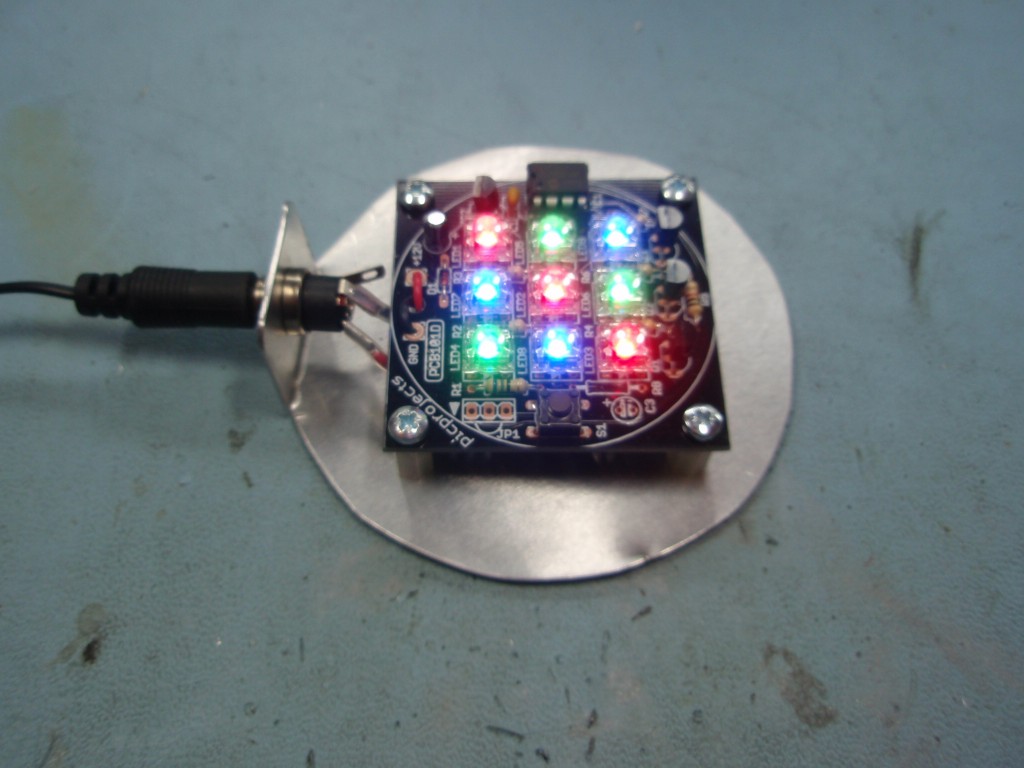
Once the PIC
microcontroller has been correctly
installed into the IC1 socket apply power
to the board. The LEDs should now
light and start fading through various
colours.
The
light from these LEDs is very intense when
viewed on-axis so you should avoid looking
directly into them when the board is
operating.
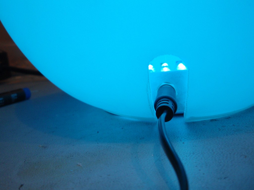
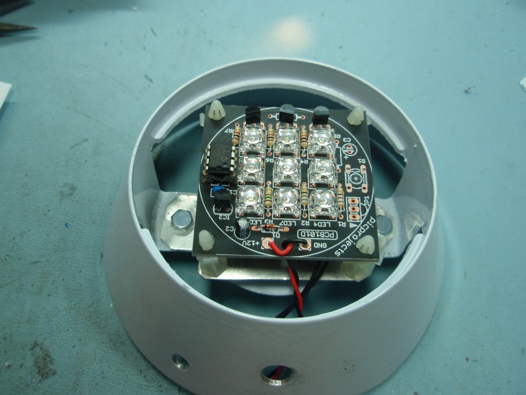
Photo. 24
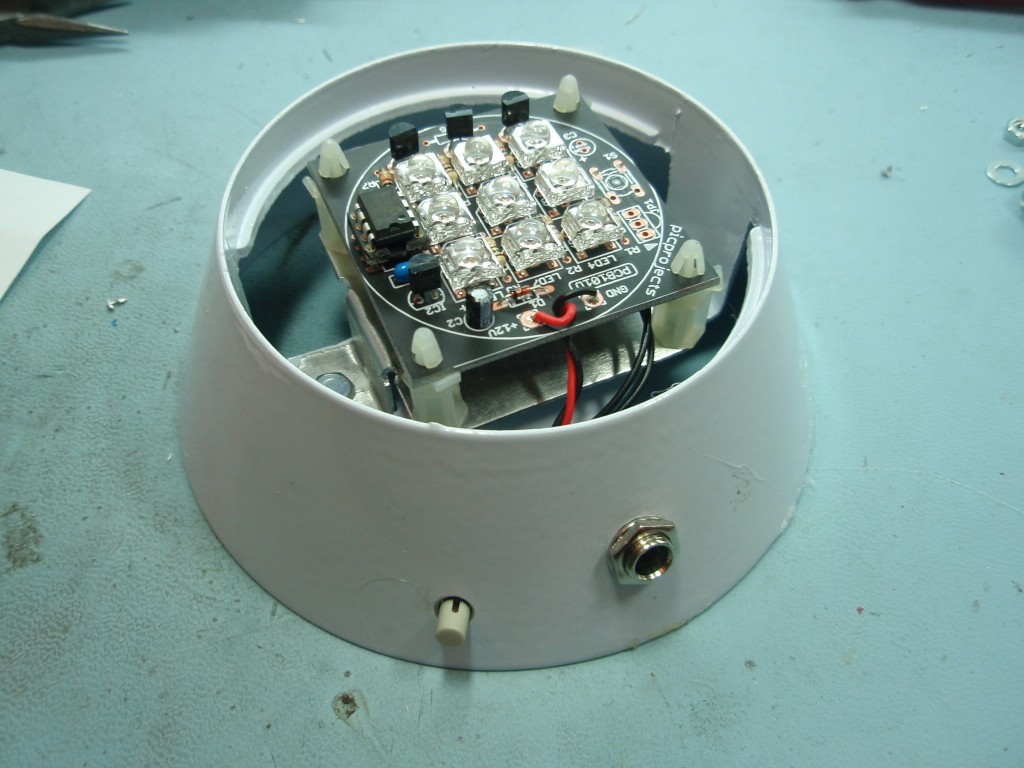
Example of
how the board can be used. A small
round frosted glass table lamp bought from
a DIY store. Remove the original bulb
holder fitting and sit the RGB LED Mood
light board inside for a stunning effect.
More
info' here
(this
particular lamp was bought from B&Q
in the UK, type Athens Small Glass Table
Lamp White, price £8.98 - Summer 2010)
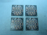
Some additional
photographs of the PCB being
assembled can be seen here.
These were taken when I was
building up four RGB Mood lights
for Christmas presents.
LED
options
The
PCB101D was designed so it could
be used with both 5mm LEDs using a
0.1" lead spacing as well as the 4
lead square Superflux type
LEDs. The kit is supplied
with the Superflux LEDs but if
you're building your own version
you have the choice of LED type to
use.
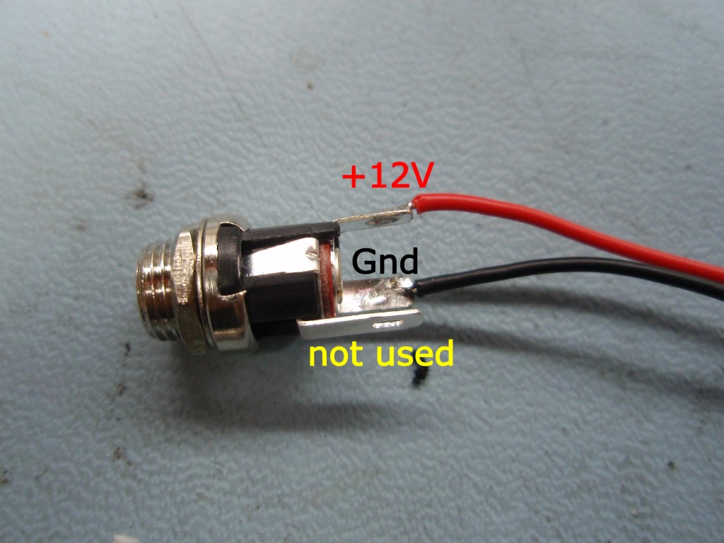
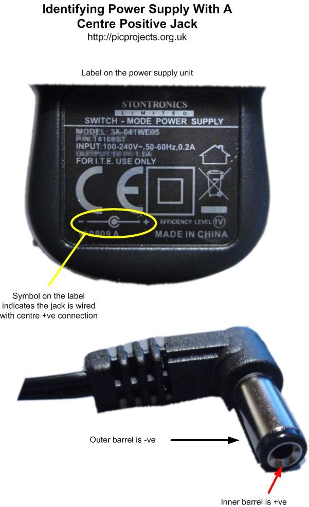
Wiring the
DC Power Jack
If you bought
the DC Power Jack option from the on-line
store you should wire the terminals as
shown below. The centre pin will then
connect to the red +12V wire and the outer
barrel to the black Gnd wire. This
is suitable for use with the majority of
plug top style power supplies wired with a
centre positive terminal
DC Power Jack
(DCPWR21)
Please note this applies
only to the DC Power Jack supplied as a
kit option; if you source your own
connector its terminals may be wired
differently and you will need to
establish this yourself.
The RGB LED Moodlight
requires a 12 volt regulated DC power supply rated
for 200mA or higher. This is important, a
non-regulated 12 volt supply may actually output 14
or 15 volts and this will damage the LEDs over time
unless you alter the current limiting
resistors. The power supply must also output
DC not AC.
Avoid halogen down
light transformers unless they are specifically
designed for operation with LED lighting since many
supply unfiltered DC or even AC which is unsuitable.
Also don't use Constant Current power supplies
designed for LED lighting with this board.
Many downlight transformers will not work correctly
without a high power load connected to them.
(Halogen type down lights use 20-50watts, the LED
mood light uses about 1 watt)
You can get plug top
style power supplies from many places including eBay
where there are good deals to be had. In the
UK you get them online from Rapid
Electronics
If you're buying a
power supply to use with the DC power jack option
available from the on-line store, the barrel
connector on the power supply needs to be 2.1mm
(this refers to the diameter of the hole in the
middle)
Any of the following
power supplies from Rapid Electronics are suitable
and if you look at these it will give you an idea of
what you need if you're sourcing from elsewhere.
5W Switch mode
plugtop PSU Euro Plug 12V 420MA Rapid Part #
85-3732
Plug & Go 12vdc
6 watt
(EUP)
Rapid Part # 85-3703
12vdc 1amp CCTV
Smpsu
(EUP)
Rapid Part # 85-3770
12vdc 15watt UK
Smpsu 2.1 C+ve
(EUP)
Rapid Part # 85-3737
Part numbers
correct as at September 2010
To summarise then,
you need a 12 volt DC regulated power supply
capable of delivering at least 200mA of output
current (a higher current rating is fine, but it
must be 12 volts DC)
This is something I put
together in the workshop in 30 minutes, I'm sure you
can do better but this gives you an idea of what you
can do.
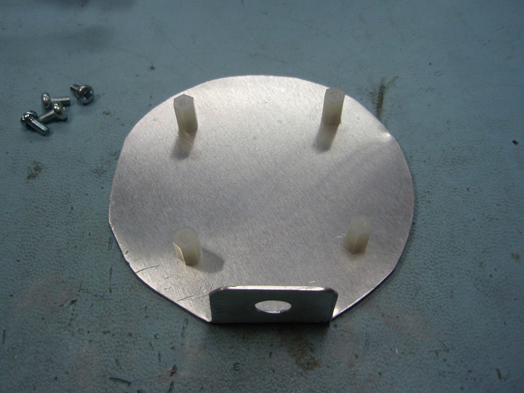
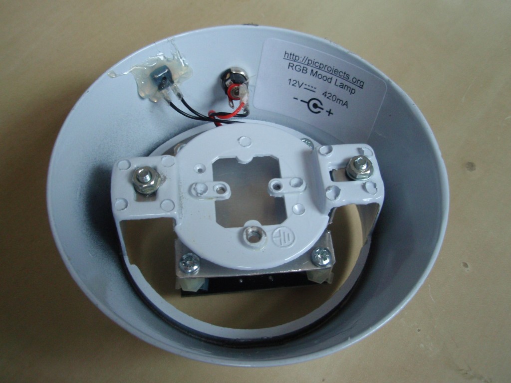
This was made using a
lamp bought from B&Q in the UK, type Athens
Small Glass Table Lamp White. The base plate
is made from 1mm aluminium sheet cut and shaped as
shown. Holes are drilled for the PCB mounting
spacers and the DC jack socket. The aluminium
is bent and then 4No 10mm nylon hex spacers are
fitted with 4mm M3 counter sunk machine
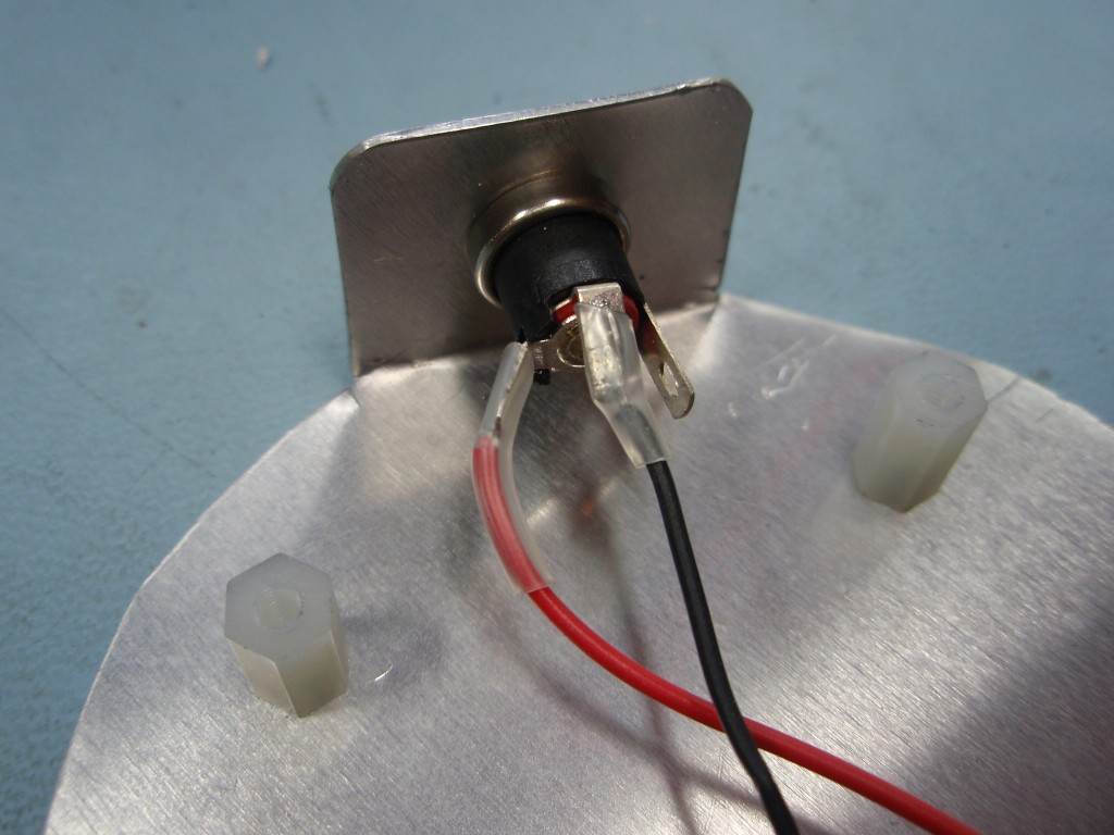
screws. The DC socket is fitted to the angled
bracket (note the use of insulating sleeving on
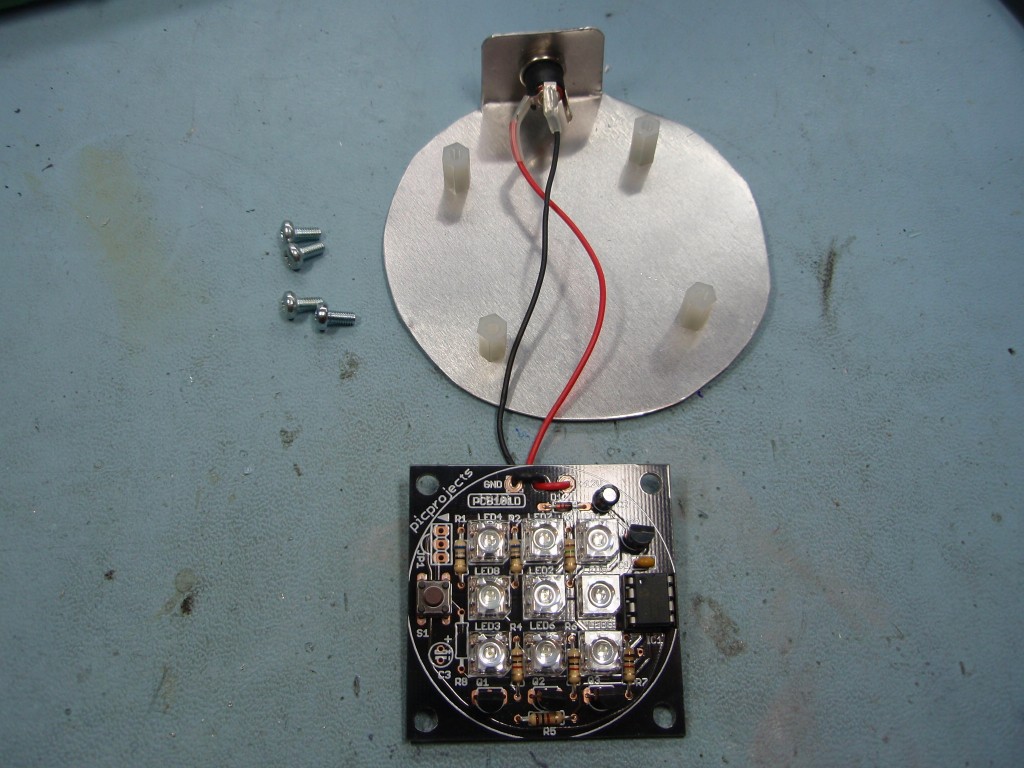
the terminals). The assembled LED Mood
Light PCB is then fitted to the base using 6mm M3
machine screws. The lamp bowl already
had a slot in the side so when it is placed over the
Mood Light assembly the power cable has room to pass
through.
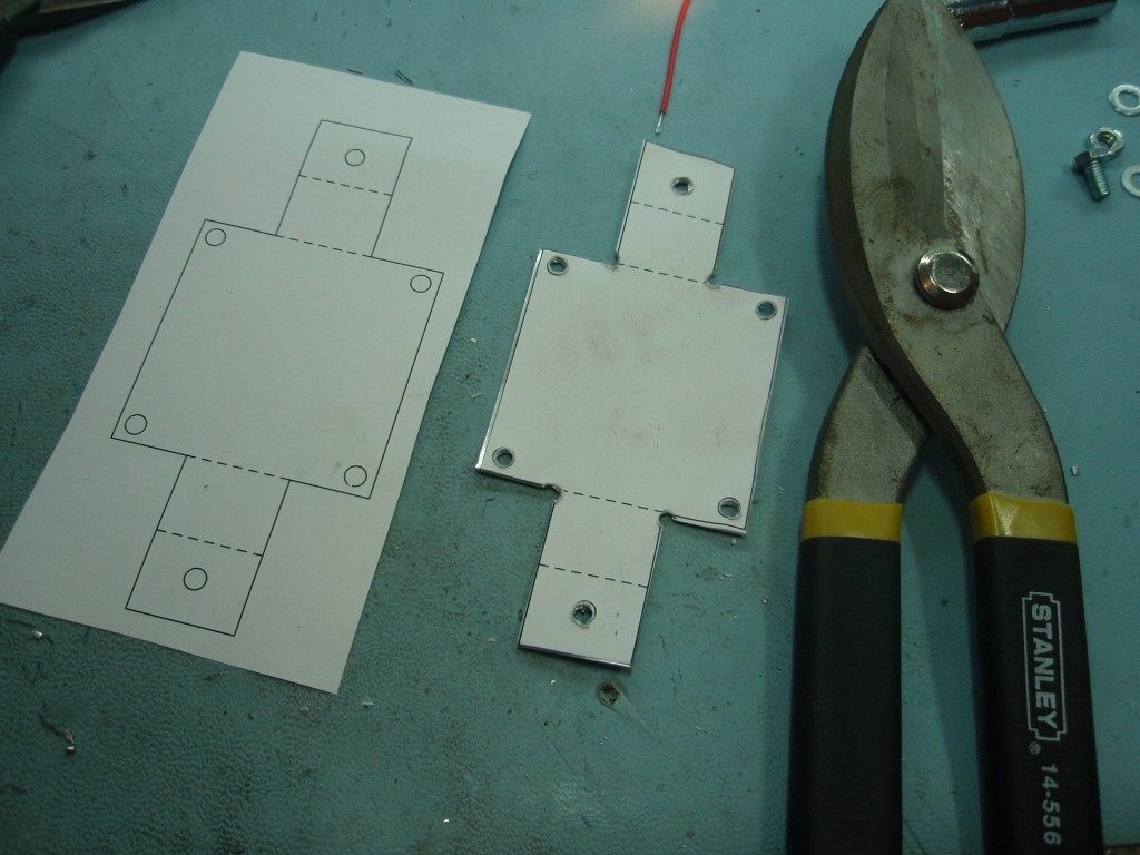
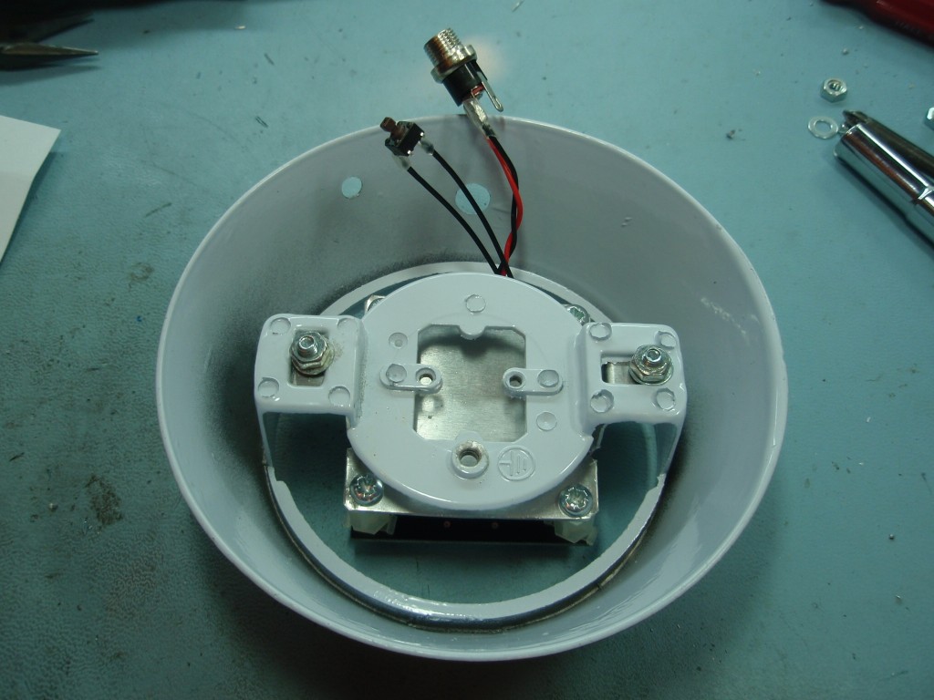
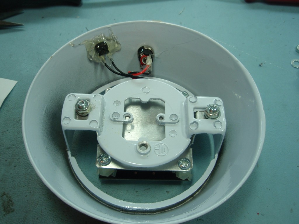
This is another mood
light I made up for Christmas presents. Again
these are based on a light fitting bought from a DIY
store. Since I was making five of these I drew
up a template in Visio so I could print five
copies. The template was stuck to the 1mm
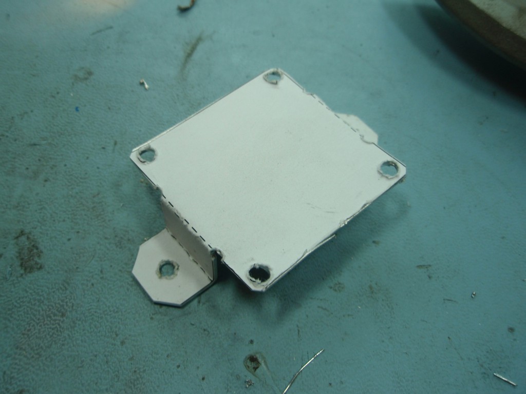
aluminium sheet using 3M Spray Mount glue. The
aluminium was then drilled, cut and shaped to fit
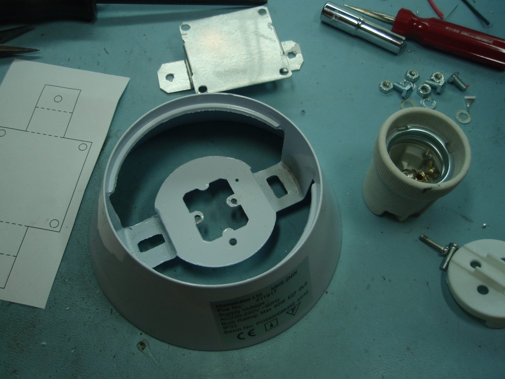
inside the lamp base. The original light
fitting was removed from the lamp base and the newly
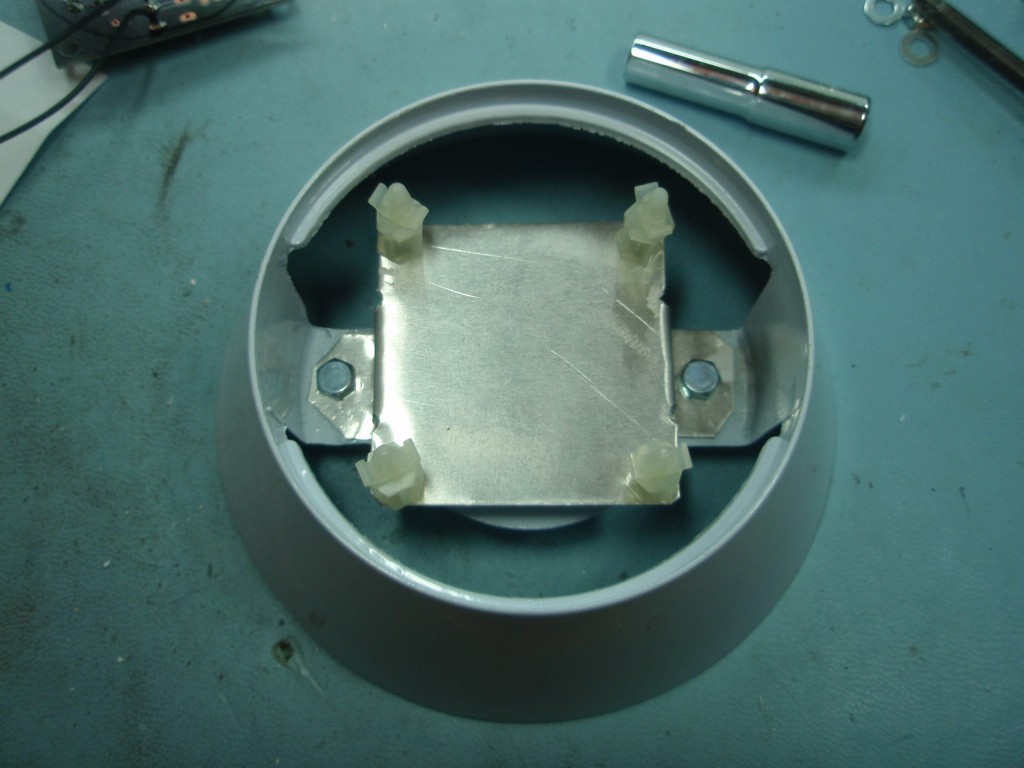
fabricated bracket installed. The PCB is
fitted to some 12.7mm PCB pillars. Holes are
drilled in the base for the DC power jack and the
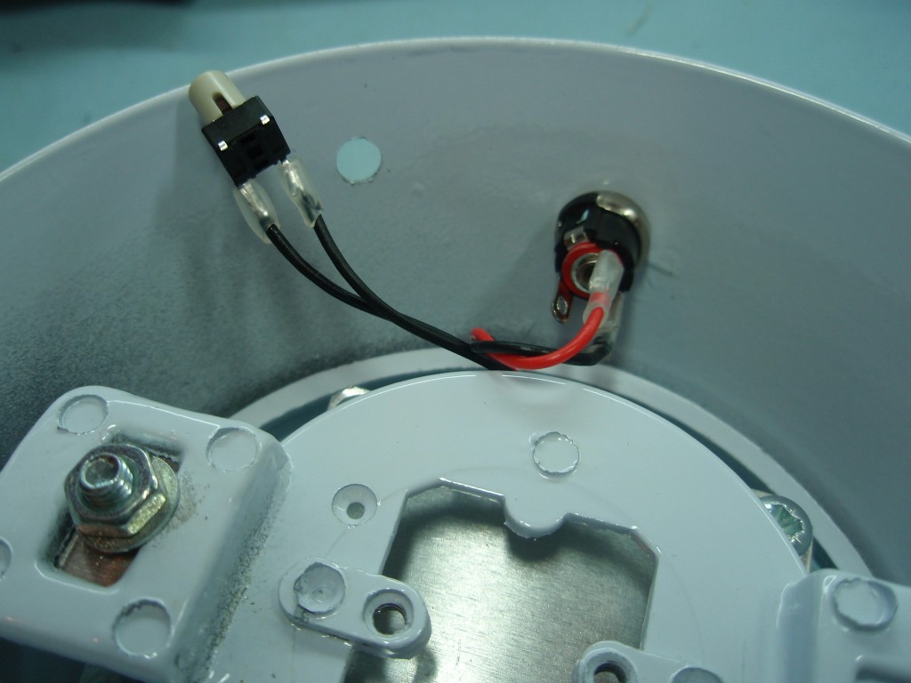
mode switch. For this light the switch is mounted
off the PCB on short leads. Note the use of
heat shrink sleeving on the leads where they are
soldered to the DC jack and switch. The switch
is fixed in place using copious amounts of hot melt
glue.
When the PIC is
first powered on after programming, it should
start running the first RGB sequence found. If
you're using the original sequences supplied with
the code here it will run a sequence of fading red
thru blue thru green repeating.
User control of the
RGB Driver is done using the S1 switch which
performs multiple functions as described in the
following section.
Single press to Hold / Run current sequence
You can press S1 at any time to stop the sequence
running and hold the colour being displayed at
that moment in time. Pressing S1 again will
start the sequence running.
If the controller is powered off while in the hold
state when it is next powered on it will remain in
the hold state displaying the same colour.
Double press to Select Next Sequence (press S1 twice less than 0.5 second apart;
think 'double-click' computer mouse button)
Step through all available sequences. When the
last sequence has been reached it will go back to
the first available sequence. Each time the
S1 switch is 'double clicked' the RGB LED PWM
values are set back to 0 (LEDs off) and the new
sequence will start running.
When stepping through the sequences it always
starts each new sequence in the Run state, even if
it was previously in a Hold state
( the last sequences is indicated by 3 short
blinks of the blue and green LEDs repeating)
Press and hold to enter / exit sleep state Press and hold S1 switch for about 1.2 seconds
to put the PIC into sleep mode. Once in
sleep mode, press the S1 switch for about 2
seconds then release it to wake the PIC from
sleep. If the S1 button isn't held for two seconds
the PIC returns to sleep
About 10 seconds
after the S1 switch is last pressed the currently
selected sequence number, RGB colour values and
Hold state are saved to non-volatile EEPROM
memory. When the RGB LED driver is next
powered on, the saved sequence number is read back
and will automatically start running the
sequence. If it was in a Hold state at power
off it will power on and remain in the 'Hold'
state until S1 is pressed again.
Anytime the PIC is
put into sleep mode by holding S1 switch down, the
currently selected sequence, displayed colour and
Hold state will be saved to EEPROM.
The HEX file is ready
to program directly into a PIC 12F629. The zip
file contains the source code which you can modify
or just view to see how it works. If you are
going to modify the code I recommend you download
and install the Microchip
MPLAB IDE which will allow you to edit, modify
and program the PIC seamlessly.
If you need a PIC
Programmer I strongly recommend the Microchip
PICKit 2, this is available from suppliers
world wide or direct from Microchip. It's
reasonably cheap to buy and reliable.
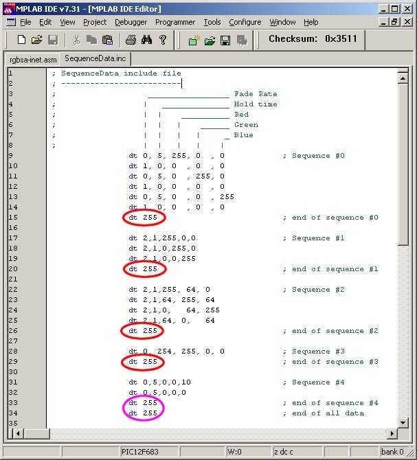
The data used by the application for
the RGB sequences is held in the file 'sequenceData.inc'
You can edit this file to add, remove or change the
data provided. You must ensure that it follows
the format described. In particular pay
attention to the 'end of sequence' and 'end of all
data' markers and also ensure that each line of
sequence data contains five comma separated entries.
(see screen dump below)
A really useful on-line utility for simulating the
sequences can be found here:RGB LED Simulator (thanks to Marek
'Marki' Podmaka for creating and sharing
this simulator)
In the screen dump above note the
'end_of_sequence' markers circled in red and the
'end_of_all_data' marker circled in purple.
You must have at least one sequence
present up to a maximum of 256 individual sequences,
although you're likely to run out of available
memory on the PIC before you reach this limit.
Each line of data starts with a
'dt' (data table) assembler directive.
All data is specified using
decimal values.
Each data value must be
separated by a comma
The sequence data on each line
has five fields:
Fade Rate: speed the colours
fade from the current values to the new
values. Each step occurs at an interval of
5ms x Fade Rate.
Fade Rate value
of 0 indicates the RGB values will be
updated immediately without fading.
Fade Rate value
must not be set to 255 except to
indicate end of sequence. (see e. below)
Hold Time: after fade
completes, delay before moving to next line
of data. Interval is 50mS x Hold Time
Hold Time value
of 255 following a Fade Rate of 255
indicates end_of_all_sequence data.
Red
PWM value. 0 = 0% (LED off) through
to 255 = 100% (LED fully on)
Green
PWM value. 0 = 0% (LED off) through
to 255 = 100% (LED fully on)
Blue
PWM value. 0 = 0% (LED off)
through to 255 = 100% (LED fully on)
Typically
changes in LED brightness are more
noticeable between 0 and 128 than from
128 to 255.
End of the current sequence data
is indicated by the Fade Rate field being set to
'255'. When the application encounters
this it restarts the sequence from the
beginning.
At the end of all available
sequence data both the Fade Rate and Hold Time
fields must be set to '255'
After editing sequenceData.inc
the file should be saved and the
rgb101g3_main.asm reassembled. The resulting rgb101g3_main.hex
file can them be programmed into the PIC