Recently
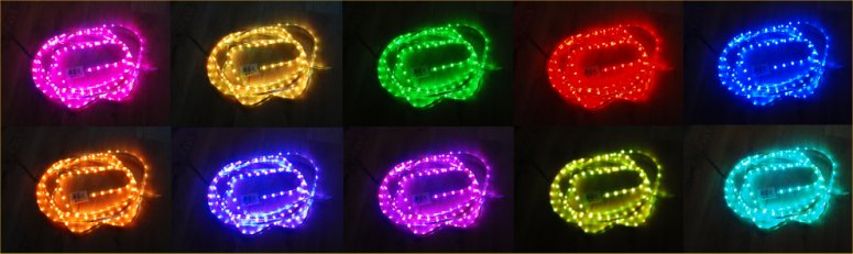
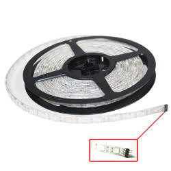
I acquired a 5M length of RGB LED strip using SMD5050 RGB LEDs.
It has built in current limit
resistors designed for
operation from a 12 volt supply. Having thought this would
directly attach to the Picprojects
MOSFET RGB LED driver project
I went ahead and bought one only to discover when it arrived that it wasn't going to be that easy.
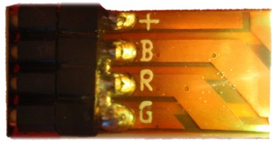
Despite the description and
markings on the supplied strip indicating it had a common anode
connection it is in fact common cathode. The terminal marked
'+' in the photo below is a common ground connection - go figure?
What is required is a high-side
driver so the three LED anodes can be controlled by the PWM output
from the PIC microcontroller while the common wire connects to
ground.
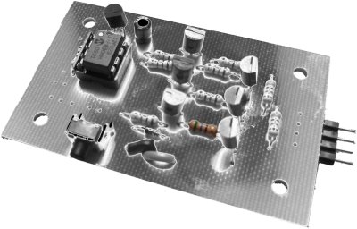
With the requirement defined I
decided to put together a quick project to work with the LED strip. The
controller on this page is an adaption of the
RGB Mood Light 101 project, firmware is
the same and can be downloaded
from that project page.
You should be aware that not all
LED strips use a common ground, I have 1 metre strip that is wired
with a common '+' or high-side and works pefectly using the
Power MOSFET RGB LED driver
kit 106 See my notes on LED
strips here
Please note:
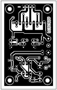
This project is NOT available as
a kit, or PCB nor can I supply the LED strip.
The circuit is essentialy the same
as the RGB101 Mood Light project and uses exactly the same fimware.
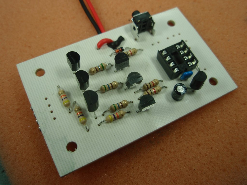
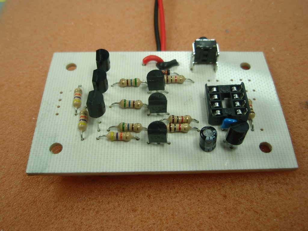
Where it differs is in the LED output drive stage. Instead of
the BC548 transistor (Q1-Q3) driving the LEDs directly they are used
to switch a second set of transistors (Q4-Q6). These are
STX790A medium power PNP transistors switching the 12 volt or
high-side of the power supply.
The current rating of each colour
in the strip is around 1.5 amps which needs a medium power
transistor to control it. I've avoided using a P-channel
MOSFET as they are both expensive and less easy to obtain.
The transistor used for the final
output is an STX790A rated at a maximum
collector current of 3 amps, with a minimum current gain of 100.
The LED strips I used require about 1 to 1.5 amps per colour.
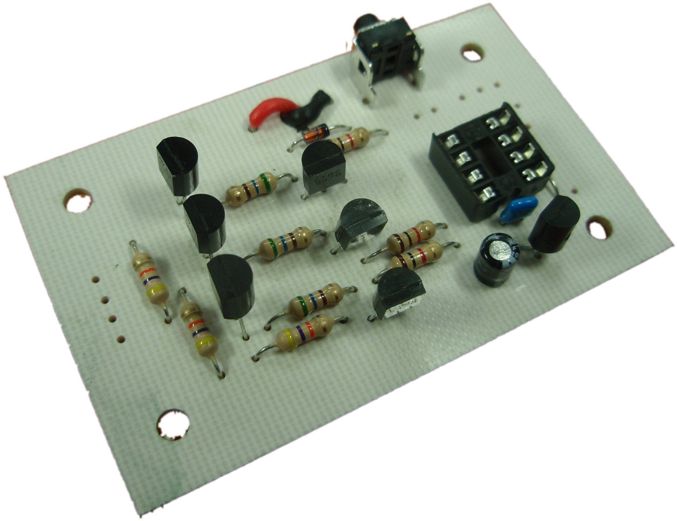
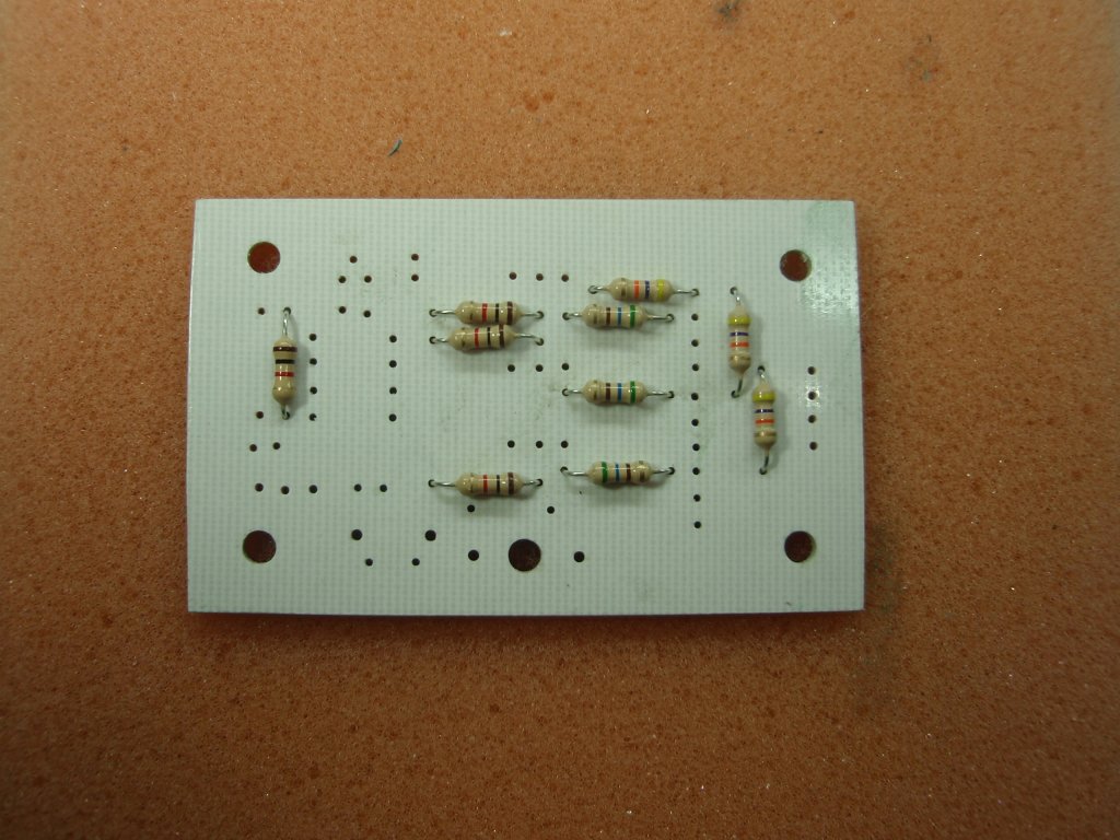
Base current for Q4-Q6 is derived from the collector current of the BC548 transistors
(Q1-Q3) via R1 - R3. Resistors R1-R3 provide around 20mA of base current
to the STX790A. I've used 560R 0.25 watt carbon film resistors
here, they are operating right on their power dissipation limit for
a 0.25 watt resistor. Since the transistors are driven with a
PWM signal average power dissipation is lower so not an issue.
If you decide to use an alternative
transistor type for Q4-Q6 and need to increase the base current
you'll need to use a 1/2 watt resistor or go for a metal film 0.4
watt or 0.6 watt which are the same physical size as a 0.25 watt
carbon film.
For Q1-Q3 any small signal NPN
transistor will work. BC546, BC547 or BC549 are also suitable
and have the same pinout as the BC548.
If you need more than 2 amps per
LED channel you will need to do some redesign of the final
transistor output section since the circuit is not designed to
handle more than 2 amps on each channel.
The rest of the circuit is straight
forward.
The 12 volt input to the board is
fed through D1 to a 78L05 5-volt regulator (IC2). D1 provides
reverse polarity protection to the regulator though it should be
noted this does not protect the LEDs and final driver transistors
since due to the high current requirements of the LED strip it is not
practical to use a diode here.
Capacitor C1 provides decoupling of
the 5 volt supply. Capacitor C2 provides filtering on the
input side of the regulator. C1 should be as close to the PICs
Vdd/Vss power input (pins 1/8) as practical. The 78L05 and C2
should also be reasonably close to each other and the PIC. R7
provides a pull-up for the PICs MCLR reset input.
S1 is the mode control switch.
JP3 just provides a pair of 0.1" spaced pads for connecting a remote
switch if the board is built into a housing.
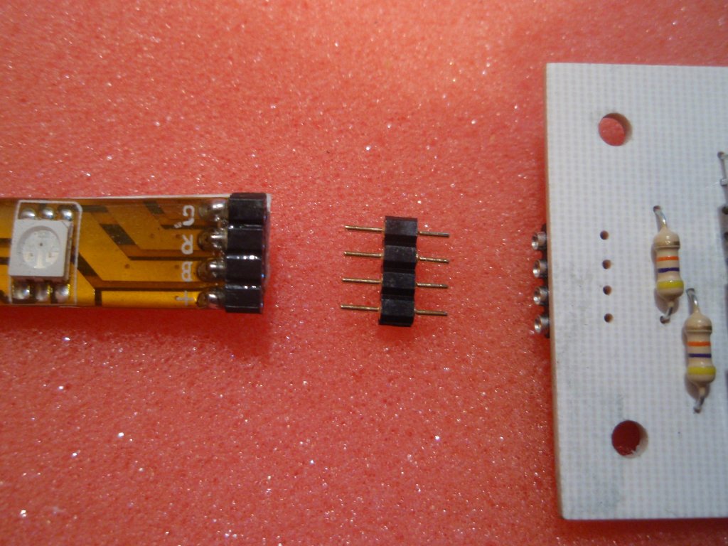
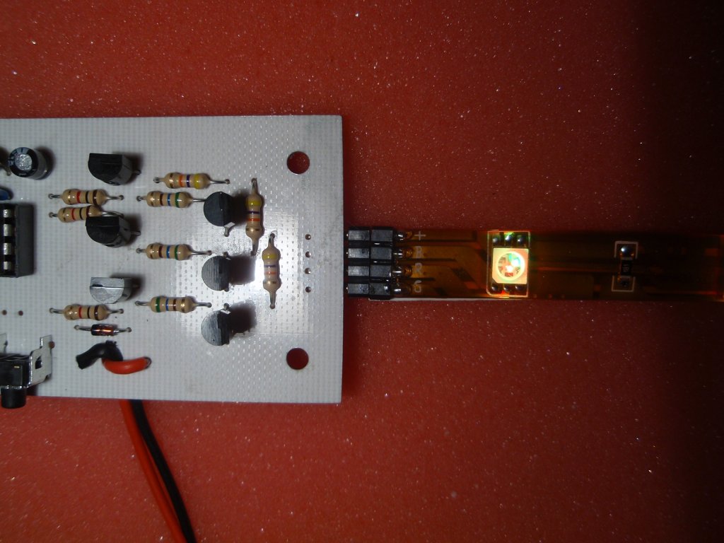
JP2 is the LED output connector.
Take note of the connections on this. The ground, red, green
and blue connections have been placed to match the LED strip I was
using. You should verify the connections to the specific LED
strip you use to ensure they are the same. (see
notes on LED strips here)
Also remember the board switches
the high or 12 volt side with the ground connection being common to
all three LED colours. If you have a common anode strip
you will need the Power MOSFET
project.
R8/C3/JP1 are not used, do not fit
components.
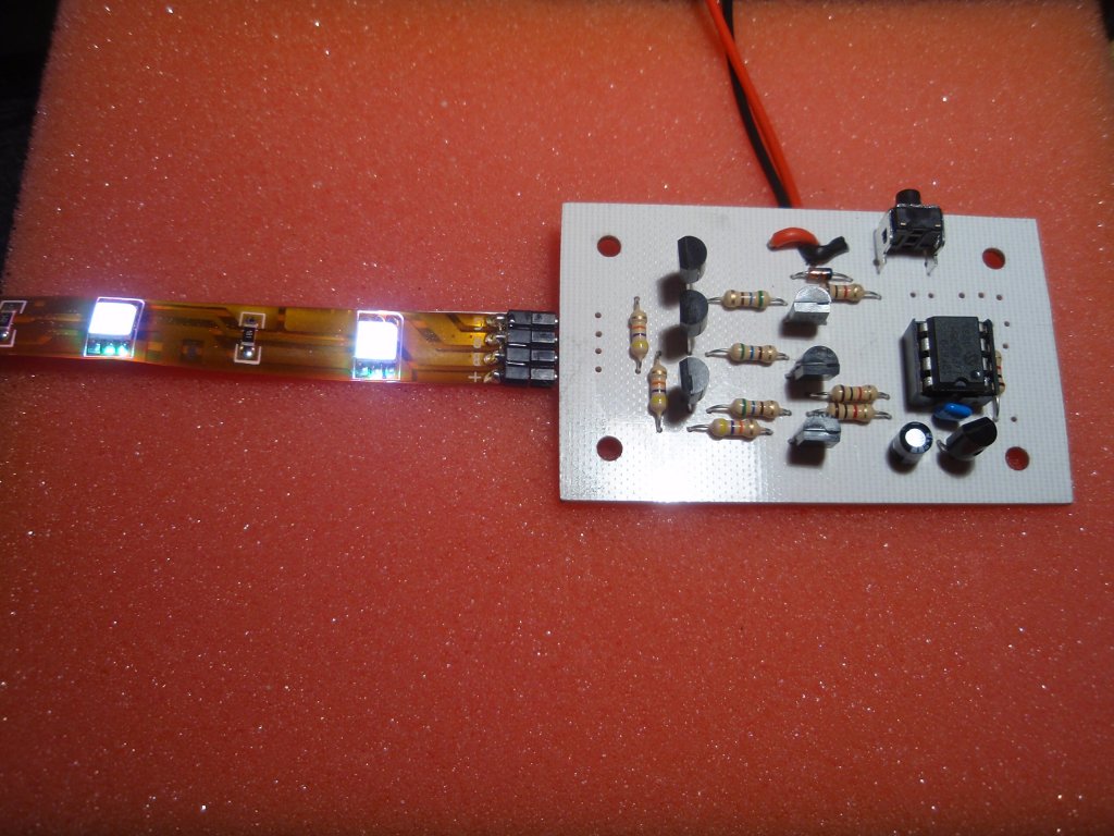
Power to the board is fed via the
two connections marked Gnd and +12V. Be sure to use a 12 volt
DC regulated power supply rated at 2-3 amps. Also note the
hole on the PCB between the power connection pads. Pass the
two power connecting wires through this to provide mechanical strain
relief for the wires/solder joint (see construction photos
further down the page)
STX790
datasheet