|
Power
MOSFET RGB
LED PWM Driver #106
for PIC12F6xx
|
 |
|
New, May 2019
Revised PCB design available at EasyEDA/Picprojects
You can also get these boards manufactured by JLC PCB direct from the EasyEDA website |
Description
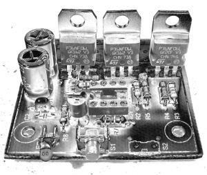
| Since I published the original RGB LED
driver (photo right) I've had many enquiries from people
asking how they could make the original board work with
more LEDs. I'd already made a couple of custom
boards up for myself, so I finally decided it was time
to put together one for the website.
The RGB LED driver
described on this page uses logic level 'N' channel
MOSFETs which allow it to control LED arrays or lamps at
up to 3 amps per channel without heatsinks.
The driver uses exactly
the same firmware as the small RGB LED driver so you can use the same code and
sequences with this board to control big arrays of LEDs. |
original RGB driver |
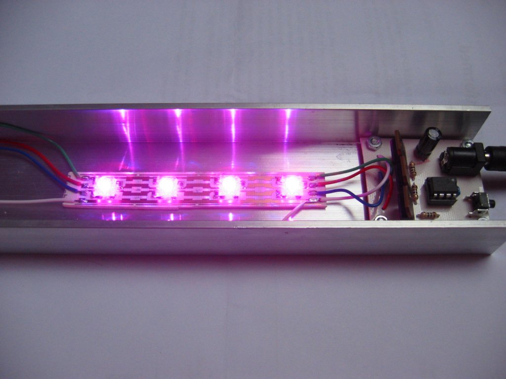
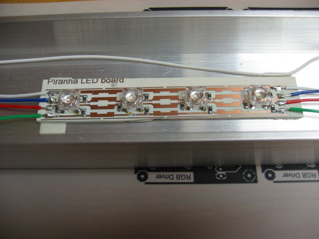
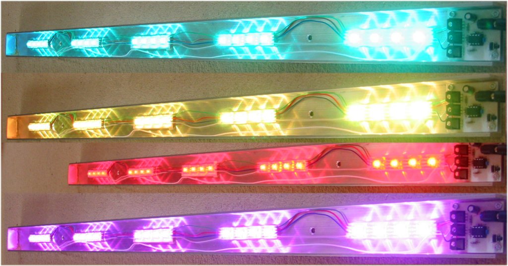
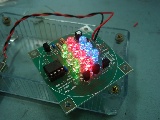
Piranha LED colour
bar
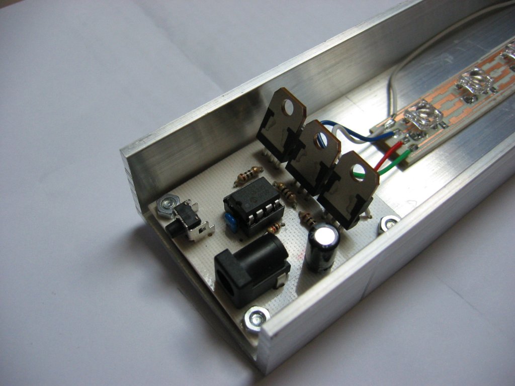
Here's a one off light
bar I built using 20 Piranha RGB LEDs and the (prototype) MOSFET driver
board. Assembled into a 25mm x 50mm x 1000mm aluminium 'U'
section. This was fitted under a wall shelf to illuminate the
floor. It's very bright and gives a nice even illumination
without any additional diffuser.
Schematic

Download
schematic in PDF

Circuit Description
This circuit is essentially the
same as the smaller RGB driver using the 5mm LEDs elsewhere on
this website except that this version uses high power MOSFETs
capable of sinking 3 amps on each channel without heatsinks
(at 5amps the MOSFETs will run hot)
The input power to the board
must be regulated DC and be capable of suppling the power
requirements of the output load.
The circuit will operate from a
supply voltage in the range 9 to 18 volts. This voltage
range is dictated by the input requirements of the 78L05 voltage
regulator and capacitors C3/4.
Switch S2 is not used with the
firmware on this website and you do not need to fit it.
I've incorporated it the PCB design because I've written some
customized versions of the code that did require two switches.
How much power can it
handle?
During testing I connected the
controller to some 50W / 12Volt halogen downlight bulbs, one on
each channel then ran them at 100% PWM duty cycle.
| Ambient temperature
during test |
22oC |
|
| MOSFET temperature
after 5mins (measured on metal tab) |
52oC |
|
| Current (sink per
channel) |
4.4A |
|
| Voltage drop across
MOSFET Source-Drain terminal (measured) |
20mV |
|
Based on these measurements and
the specification of the MOSFETs and PCB connectors, the
controller should comfortably handle 3 amps per channel.
While the individual MOSFETs could handle more current, the PCB screw terminal connectors are rated at 16 amps
and since there is only a single Ground connection to the board,
total load for the three RGB channels should not exceed this.
PCB
PCB only option is available to
buy
from the on-line shop page
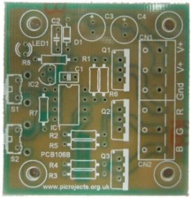
PCB Artwork
Component List

Buy the complete kit for
this project from the Picprojects
on-line shop page
You can buy all the parts
needed to build this project from most component suppliers world
wide. In the UK you can get everything from
Rapid Online and
I've included a parts list with their part numbers below.

All
Rapid parts/descriptions correct at 16-November-2008. You should
check part# and descriptions are correct when ordering in case
I've made a mistake transferring them onto this page.
| Component |
Description |
Part # |
| R1,2,3 (order 1
pack) |
PACK 100 120R 0.25W CF
RESISTOR (RC) |
62-0348
|
| R4,5,6 (order 1
pack) |
PK 100 10K 0.25W CF
RESISTOR (RC) |
62-0394
|
| R7 (order 1
pack) |
PACK 100 1K 0.25W CF
RESISTOR (RC) |
62-0370
|
| R8 (order 1
pack) |
PK 100 270R 0.25W CF
RESISTOR (RC) |
62-0356 |
| C1 |
100N 2.5MM X7R
DIELEC.CERAMIC (RC) |
08-0235 |
| C2 |
220N 5MM Y5V
DIELECT.CERAMIC (RC) |
08-1015
|
| C3, C4 |
100UF 25V LOW
IMPEDANCE ELECTROLY CAP RC |
11-2922
|
| D1 |
1N4148 SIGNAL DIODE
75V 150MA (TRU) RC |
47-3416
|
| Q1,2,3
(alternative) |
STP36NF06L MOSFET
LOGIC N 60V 30A (RC) |
47-0552
|
| IC2 |
DA78L05 V REG +5V
100MA TO-92 TRU (RC) |
47-3612 |
| LED1 |
L-34GD MIN 3MM ROUND
GREEN LED (RC) |
56-0745 |
| socket for IC1 |
8 PIN 0.3IN TURNED PIN
SOCKET(RC) |
22-1720 |
| IC1* |
PIC12F683-I/P
MICROCONTROLLER (RC) |
73-3374
|
| CN1, CN2
(order 3) |
2 WAY 16A
5MM END STACKABLE TERM-BLOC RC |
21-1810 |
| S1 |
3.85MM
RIGHT ANGLE TACT SWITCH (RC) |
78-1152 |
| |
|
|
Parts List Notes
* IC1 will need
programming with the firmware code
before use
PIC Programmer
If you need a PIC programmer you can also buy the PICkit2 starter kit from Rapid, part #
97-0101
Alternate MOSFETS
The
STP36NF06L
MOSFETs specified are logic
level devices and are specified to operate with a low gate
voltage. You can use standard N Channel MOSFETs with a
suitable Ids current rating if you can't
obtain this part and they should work fine with load currents of 2-3 amps.
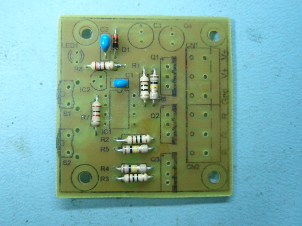
Construction photos:
Identifying components
Component id visual guide
Assembly reference image
We've also put together
step-by-step construction details for this project on the
Instructables website.
Refer to the schematic diagram for component values used in this
project.
Fig.1 |
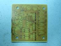
Fig .2 |
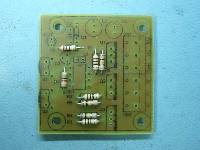
Fig. 3 |
|
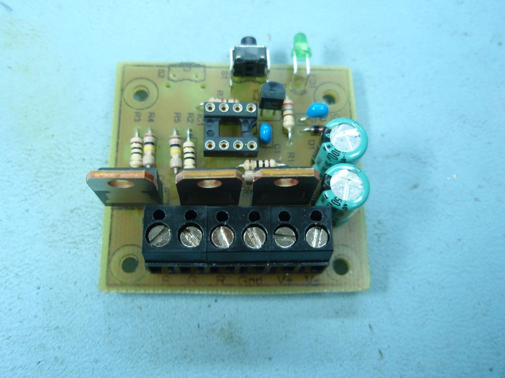
Fig 1. Before you start
make sure you observe ESD procedures when handling and
installing the MOSFETs Q1-3 to avoid destroying
them through electrostatic discharge.
Fig 3. Start assembly
with the small components first and work through to the large
parts.
|

Fig.4 |
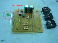
Fig .5 |
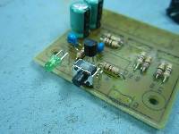
Fig. 6 |
|
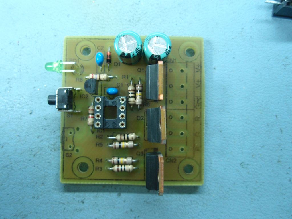
Fig. 4 When fitting D1
make sure the black band is in the same direction as shown on the overlay.
Fig. 5 The LED has its
legs bent through 90o before installation.
Capacitors C2/3 should be
installed with the negative terminal towards the middle of
the PCB.
One lead of each capacitor is shorter than the other.
The short lead is the negative terminal.
Fig. 6 Fit LED with
cathode toward top edge of the PCB, anode toward S1.
The
short lead on the LED is the cathode.
|

Fig.7 |
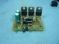
Fig .8 |
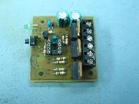
Fig. 9 |
|
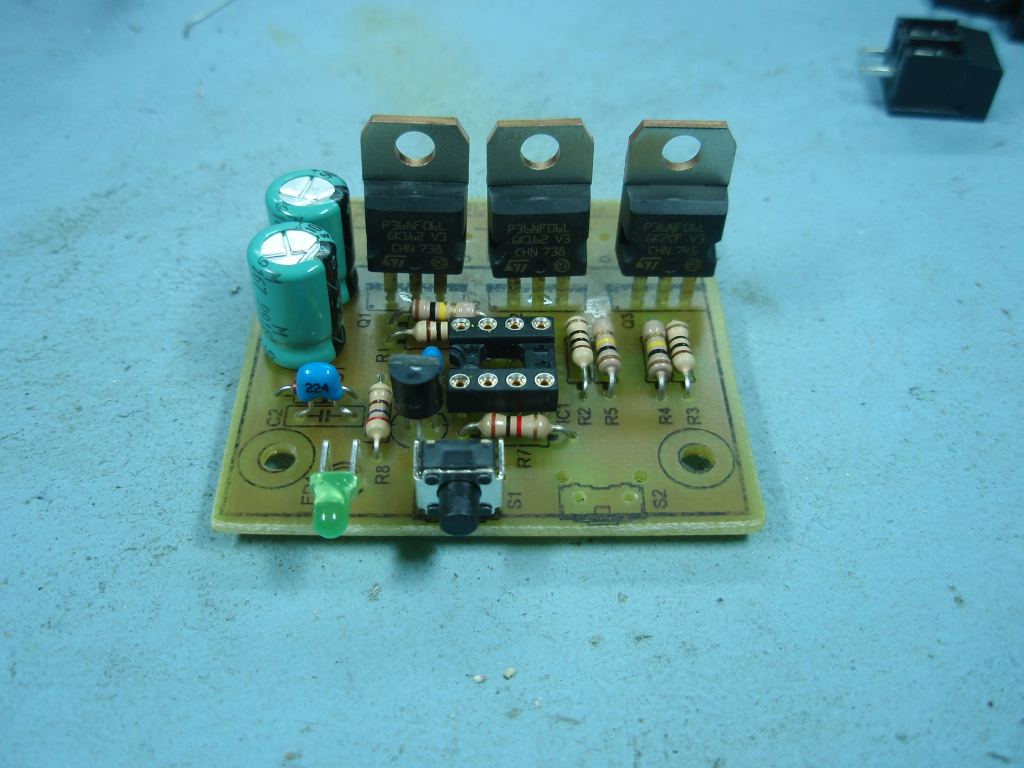
Fig.
7/8 General assembly views
Fig. 9 The PCB screw
connectors are end stackable. Slot the connectors together
before installing.
|
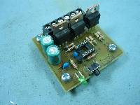
Fig.10 |

Fig .11 |
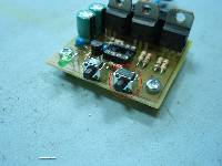
Fig. 12 |
|
Fig. 10/11
General assembly views
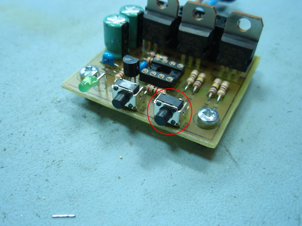
Fig.12
The PCB is laid out to take a second switch. It is not
used by the firmware and isn't required so unless you're
planning to use the hardware with your own code, do not install
it.
|
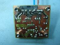
Fig.13 |
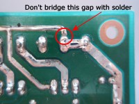
Fig .14 |
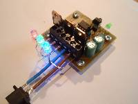
Fig .15 |
|
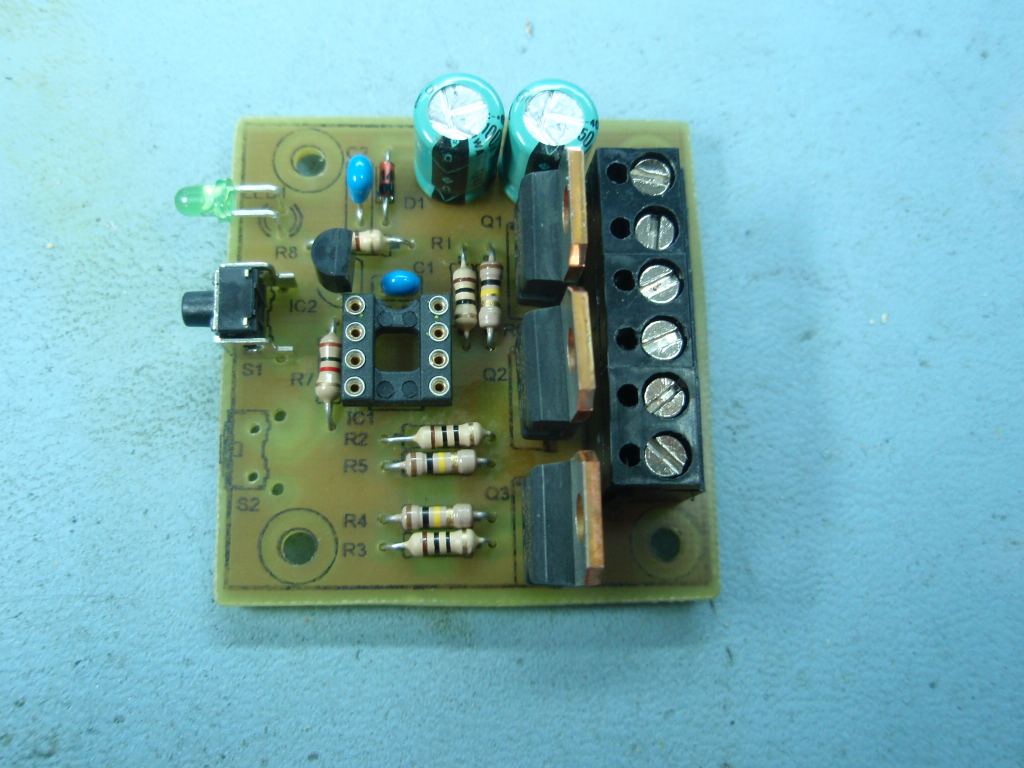
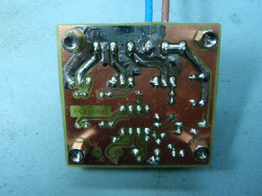
Fig.13
It is recommend to heavily tin with solder the PCB tracks between the
connectors and MOSFET to increase the current carrying capacity
of these tracks. This is shown in the photo.
Fig.14
 Don't bridge solder across the gap
indicated in the photo. Due to an oversight with the
solder mask the exposed PCB track looks as though it should be
connected - it should not. If you accidentally bridge this
point it will short-circuit the input power supply to the board.
Don't bridge solder across the gap
indicated in the photo. Due to an oversight with the
solder mask the exposed PCB track looks as though it should be
connected - it should not. If you accidentally bridge this
point it will short-circuit the input power supply to the board.
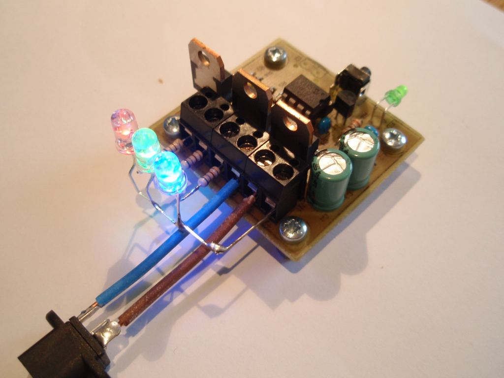
Fig.15
Testing the basic circuit function using 5mm LEDs
|
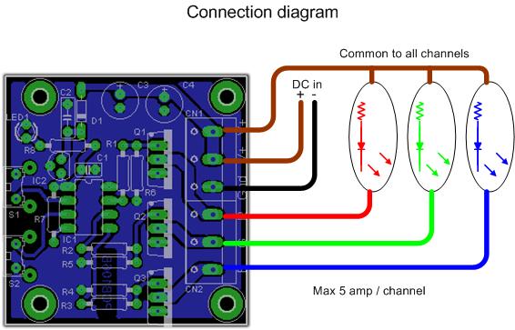
Connecting
to the PCB
DC in should be in the range 9
to 18 volts. It should also be able to supply the current
requirements of all three output channels.
Maximum output per channel is 3
amps for a total of 9 amps. Connecting cables should also
be able rated for the current they will be carrying.
LED arrays, modules etc should
have their negative or cathode terminals connected to the MOSFET
outputs and the positive or anode connection to the common
terminal as shown below.
A very good 'free' web based
tool that will design arrays of LEDs for you, check out this
site.
http://led.linear1.org/led.wiz
If you're looking for high power
LEDs and arrays to use with this driver you might want to check
out
Sure Electronics. I have no affiliation with them but
I've bought LEDs from them.
Firmware
This driver board uses the same
firmware as the RGB LED Driver
elsewhere on this website.
Please download the code from
here
Contact us:
 |