|
|
Long Period
Astable Timer
with reset, hold and
monostable functions
|
 |
Description
This software functions
as a long period astable mutivibrator. The mark and space
period can be set from 1 second up to a maximum 65535 seconds
(18h12m15s). Using the internal 4Mhz RC oscillator delays with an
accuracy of 99% or better can be achieved
The code also
implements an edge triggered reset and an active low hold function.
The reset edge can be configured for rising or falling edge.
The hold function is active low and stretches the timed period for
as long as the hold input is held low.
In addition to this up to 450
mark/space time pairs can be used which are executed sequentially
allowing complex pulse trains to be generated.
By connecting the hold input to the Q
output, the code can also be made to function as an edge-triggered
monostable timer, using the reset input as the trigger.
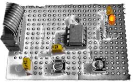
The code will run on a PIC 12F629 or
12F675.
Pin functions
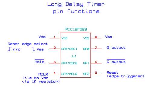
At power on and after an edge triggered reset the outputs enter a
mark state with the Q output going high and the notQ output going
low. The first time entry is then read and the code waits for
the number of seconds specified. When this period has elapsed
a Space state is entered with the Q output going low, notQ output
high and the next time entry is read.
When the Hold input is
taken low the output remains unchanged and the timer is stopped,
effectively stretching the current time period. When the Hold input
returns high, the timer continues.
If the Reset input is
triggered while Hold is low, the outputs are reset to Q == high,
notQ == low and the timer is loaded with the first entry from the
LongDelayTimes.inc file. It them remains in the Hold state until the
Hold input returns high.
Accuracy of timings
Since the timings are
generated from the PICs internal 4Mhz RC oscillator the accuracy is
subject to the tolerances specified in the Datasheet with respect to
operating voltage and temperature. The software itself will generate
an accurate timing but any deviation in the RC oscillator from 4Mhz
will result in the time period deviating. You should therefore
test the accuracy before committing it to an application.
Since the PIC
calibration word can only be correct at a specific supply voltage
and temperature it is advisable to calibrate it at the supply
voltage it will operate at in the final application. This will
help considerably in obtaining accurate timings.
My investigations with
a number of PICs from different batches suggest that Microchip
calibrate the PIC at a supply voltage of 3.5 volts. Therefore
if you're operating it from a 5 volt supply it will be running
slightly too fast.
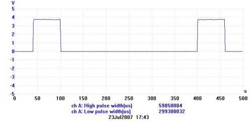
In the trace below the
factory calibration value was 0x2C, the value when recalibrated with
a 5 volt supply was 0x34. For a programmed delay of 60 /
300 seconds it is showing 59.85/ 299.3 seconds which is 99.7%
accurate. This would result in an error of 3m16s over 18h12m.
Software to recalibrate the internal oscillator in the
12F629/12F675 is described
here
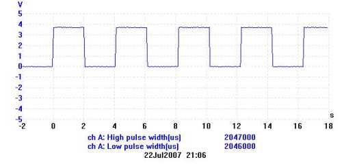
Example of time
settings and output
Examples below illustrate
the time entries in the 'LongDelayTimes.inc' file and the resulting
signal on the Q output. The inverted signal is available on the
notQ output.
;---------------------------------------------------------------
; a single
time entry generates
time 2 ; alternate
marks and spaces with 50% duty cycle
;---------------------------------------------------------------
With two entries, the
first time value is the mark period and the second the space period.
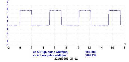
;---------------------------------------------------------------
time 2 ; mark
time 3 ; space
;---------------------------------------------------------------
If you use a number of
mark/space entries in the include file they are applied to the output
sequentially before the whole sequence is repeated. This is illustrated
below.
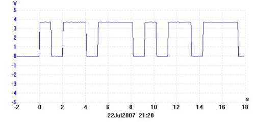
;---------------------------------------------------------------
time 1 ; mark
time 1 ; space
time 2 ; mark
time 1 ; space
time 3 ;
mark
time 1 ; space
;---------------------------------------------------------------
If you enter an odd
number of time values then with each pass through the
resulting marks and spaces in the output are inverted. This is illustrated below
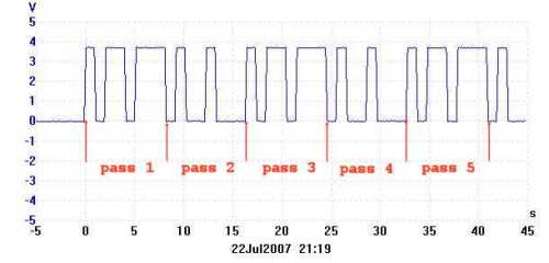
;---------------------------------------------------------------
time 1 ; mark /
space
time 1 ; space / mark
time 2 ; mark / space
time 1 ; space / mark
time 3 ; mark
/ space
;---------------------------------------------------------------
When the reset input is
edge triggered the output is immediately set to the Mark state and
timing is restarted from the first entry in the include file. This
is illustrated below
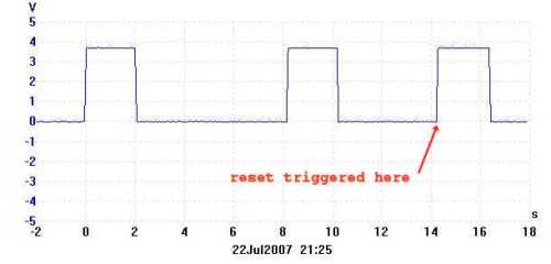
;---------------------------------------------------------------
time 2 ; mark
time 6 ; space
;---------------------------------------------------------------
When the hold input is
taken low, the output remains in its current state and the timer stops.
When the hold input returns high, the timer continues. This is
illustrated below.
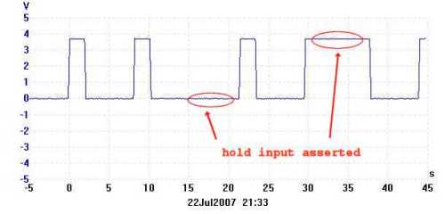
;---------------------------------------------------------------
time 2 ; mark
time 6 ; space
;---------------------------------------------------------------
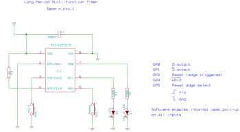
Code and schematics
This code is written for and
will assemble for a 12F629 or 12F675 device using MPLAB.
There are two files, the main code is in LongDelayF5.asm and the
timings are held in separate include file LongDelayTime.inc You will need to edit this file with your
required timings before assembling the code.
Quick guide to
re-assembling the code with MPLAB IDE can be
found here.
|
Description |
Filename |
Download link |
| Source
code for 12F629/675 |
ldt_12_int.zip
v1.2.0 07/01/2009 |
 download
 |
| HEX file
ready to program into the PIC* |
ldt_12_int.zip.HEX
v1.2.0
07/01/2009 |
download |
* The HEX file download
contains a short demo sequence comprising 1S on - 2S off - 1S on -
3S off.
PDF Version
Floating Inputs
The weak internal
pull-up feature is enabled for the reset, hold and edge
select inputs so no external pull-up resistors are required. The MCLR
input should by tied to Vdd using a 1K resistor.
Both outputs stay high
If both the Q and notQ
outputs remain high after power-on, then the calibration word at program
memory 0x3FF has been erased. For more information on the
calibration word see here
Contact us:
 |
