SIRC based IR Remote Control Information
All the work presented here is based
on information
researched on the Internet and my practical testing with
a selection of genuine Sony remote controls while developing
IR remote control projects for PIC microcontrollers.
It is in no way intended to be a definitive guide to the
Sony SIRC protocol or the SIRC standard.
Use of the information on this page is entirely at you own risk
as I make no claims to its accuracy or correctness.
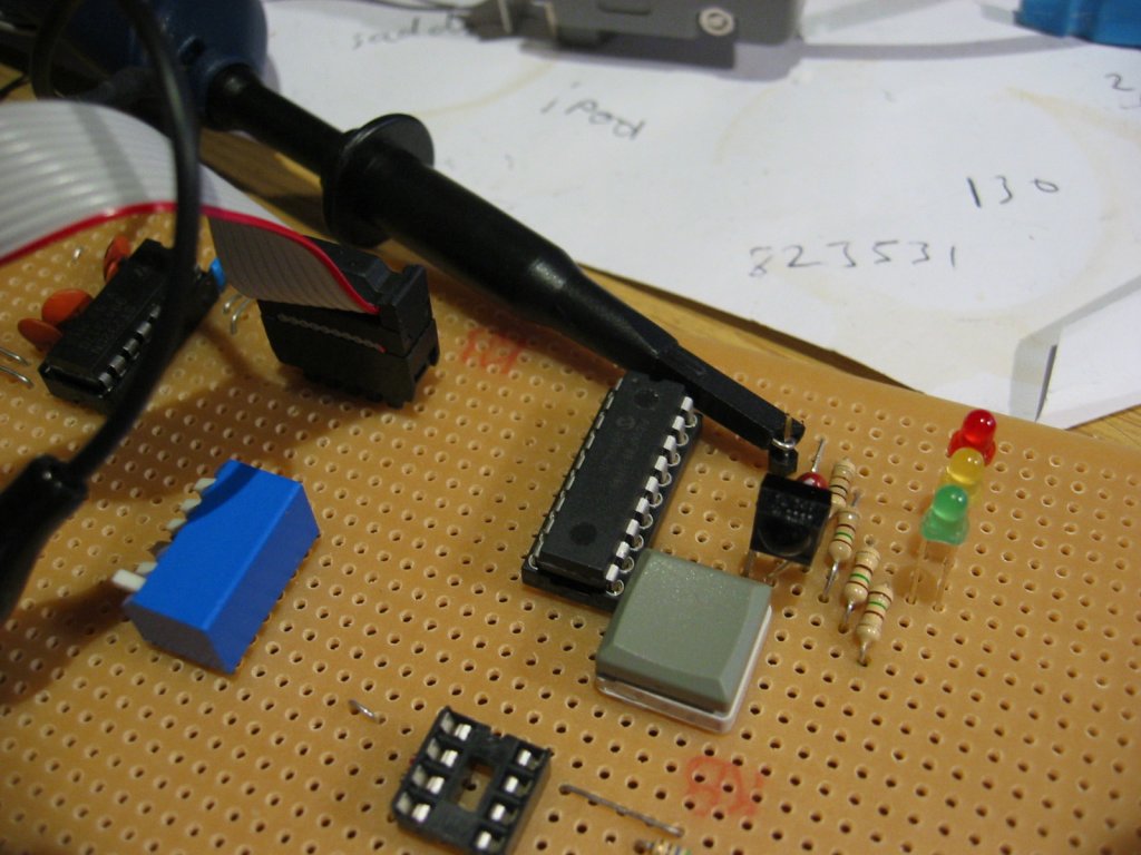
PIC based IR remote control projects
Sony SIRC IR Decoder for PIC 16F88 (development project)
Decodes 12, 15 and 20 bit SIRC data streams
Tested with following Sony Remotes;
- RM-U215
- RMT-D166P
- RM-S325
Connections:
Sample output
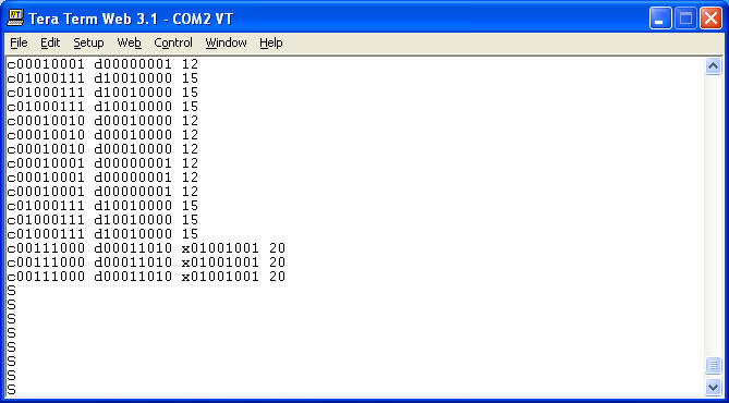
With the Sony remotes tested, a single press of any
button results in the same
code being sent three times in succession.
If the button is held down it will repeat the code
indefinitely, but always a
minimum of three times.
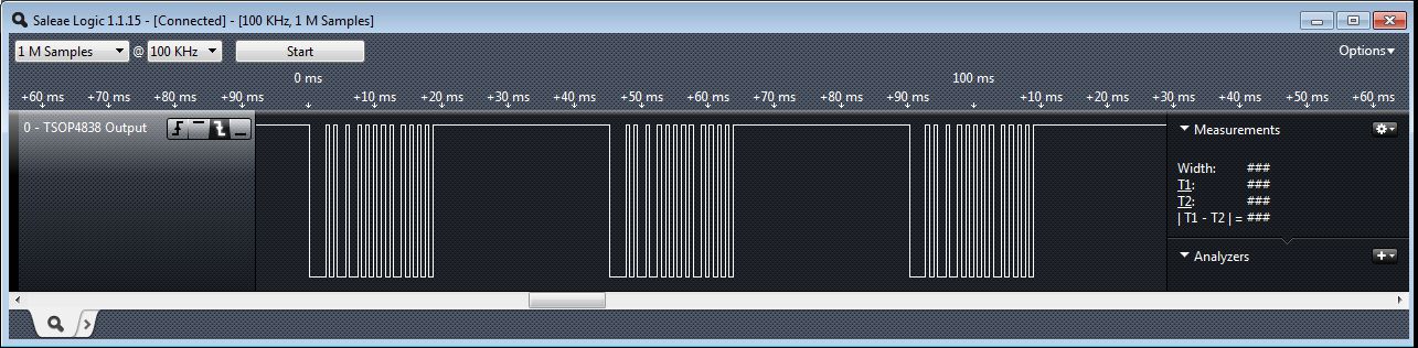
Real World Example
The section below shows the output from TSOP2238 IR PCM Receiver captured using a Salea Logic probe.
The output from the TSOP2238 is active low.
This means when it receives an IR burst from the remote
control, the output goes low. When no signal is received the output is
high.
Note: in the screen shots below
The Sony SIRC protocol use the pulse length coding method.
The length of the mark pulse is used to determine the
data. In theory just measuring the
length of the mark pulses will allow the data to be decoded, however it is best
to measure
the mark+break to avoid spurious decodes.
All the Sony remote controls tested transmit the data at least three times, and
therefore comparing two or more frames to ensure they contain the same data is
also a good idea
to ensure spurious data hasn't been decoded.
The data coding uses multiples of a period of 600uS; one 600uS period is called 'T'
In the screen shot below the '7' button has been pressed on a Sony TV remote.
The data frame is sent a minimum of three times, more if
the button is held down.
Each frame contains identical data.
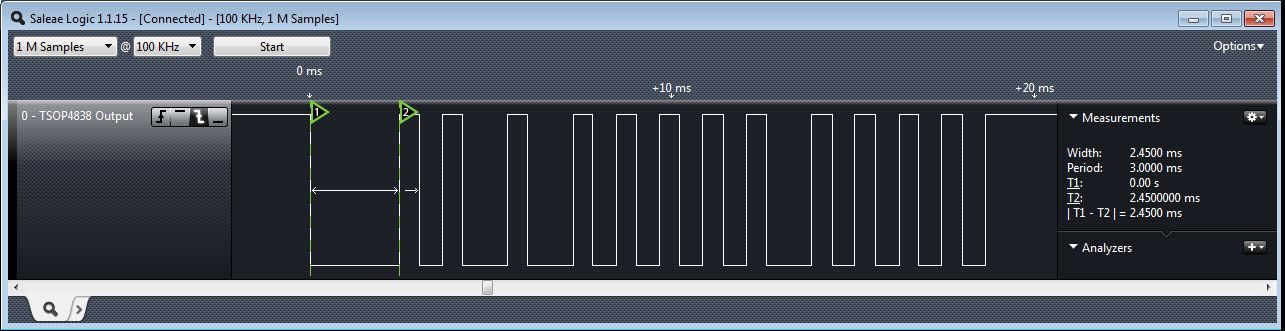
Looking at one of the three frames from above in more detail.
The start pulse is shown below. You will see from
the timing information at the right that
the mark is slightly long at 2.45mS but the overall period of the 4T mark + 1T
break is 3mS
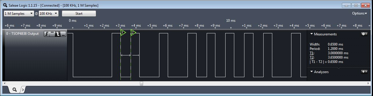
Here a '0' bit is highlighted. You see the 1T mark followed by 1T break
Again the timing information on the right shows the mark
pulse is 0.65mS but the overall
mark + break is 1.2mS.
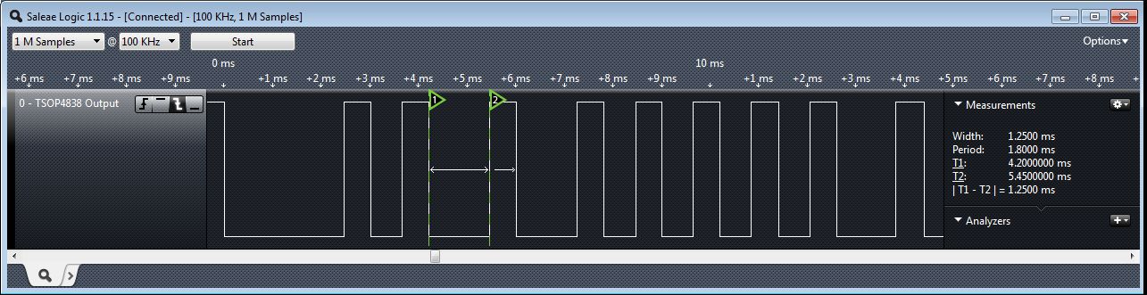
Here a '1' bit is highlighted with a 2T mark followed by 1T break
Again the timing information on the right shows the mark
pulse is 1.25mS but the overall
mark + break is 1.8mS.
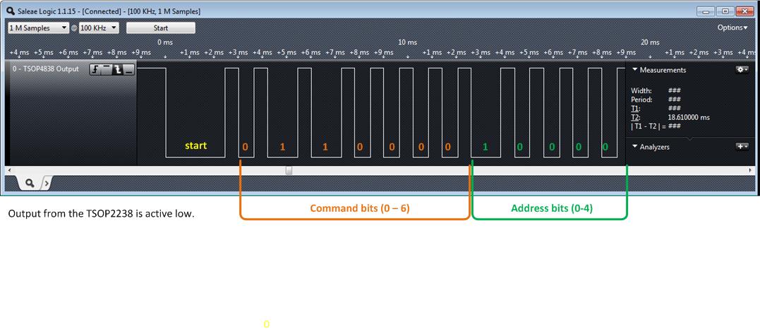
The final screen shot below shows the decoded output
from a Sony TV remote with the
'7' button pressed.
Remember that the bits are sent
LSB
first so to obtain the binary value we need to reverse
the order.
Some 12-bit SIRC device/command codes
this is not a definitive list
|
|