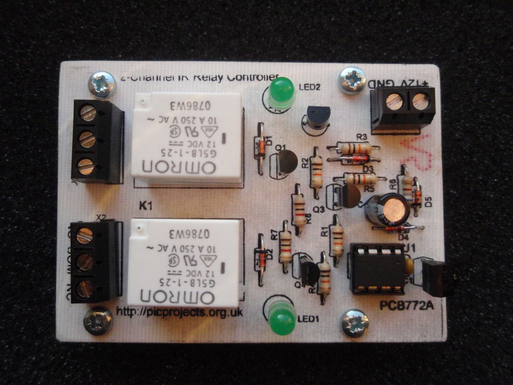
This project is a 2 channel
infrared (IR)
remote controlled relay driver with power saving. It works
with 12-bit SIRC IR signals as used by Sony remote controls.
The controller also features a
power save feature which reduces the relay holding voltage to
50% of the relays nominal operating voltage once the relay has
switched on.
The board uses Microchip's
low cost PIC10F200 microcontroller along with a handful of easy
to find components making this possibly the lowest
cost remote controlled relay driver around. Everything you
need to know to build this project, including the firmware code is right here on the project
page.
Don't
forget to check out the accompanying
mini IR
remote control which can be used with this
project.
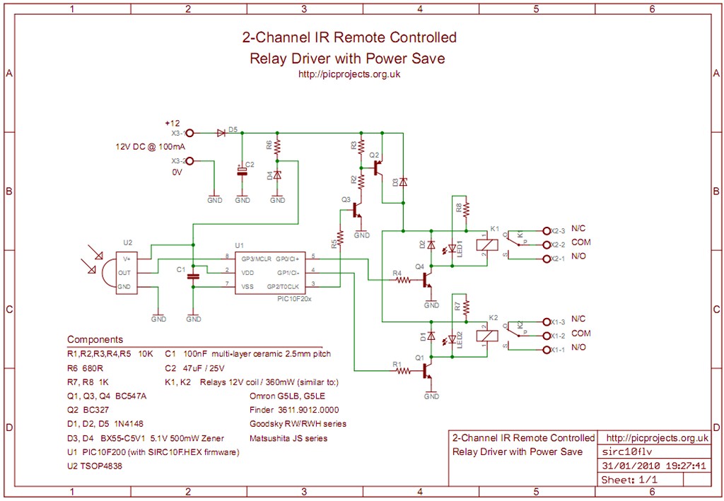
The board requires a 12
volt DC supply input. This is fed through diode D5 which provides protection from a reversed
connection of the power supply. Capacitor C2 is used for
decoupling the supply. The 5 volt supply needed by the
microcontroller U1 and the IR receiver U2 is generated using a
simple zener shunt regulator comprising R6 and the 5.1 volt
Zener diode D4.
The relays are switched on by
microcontroller U1 via driver transistors Q1 and Q4. These are low power NPN transistors, in
this case BC547 but virtually any small NPN transistor will work
here as they only need to switch around 30mA - BC548 or BC549
would also work well. Diodes D1
and D2 provide protection for the transistors against the
back EMF voltage transient when the relays are switched off.
The controller also features a
power saving control which reduces the power consumption of the
relays by around 50% when they are on. Relays of the
type used here typically need 75% of their nominal voltage to
"pull-in", once on they will 'hold' with a lower voltage.
The datasheet for the Omron G5LE for example shows a must
release voltage of 10% of rated voltage - for a 12V relay that's
around 1.2V. This circuit uses a holding voltage of around
50% or 6 Volts.
Normally the supply voltage is
fed to the
relay coils via zener diode D3 which
drops 5.1 volts leaving around 6 volts across the relay coil. In
parallel with D3 is transistor Q2. When this transistor is
switched on, it bypasses D3 and provides the full supply voltage
to the relays. This 'boost' voltage is switched by the
microcontroller with Q2 being switched on via Q3. The
firmware in the microcontroller detects when a relay is being
turned on and applies the boost for a minimum of around 100mS,
again the datasheet for the relays gives typical operate time of
10mS, so the 100mS boost guarantees the relay will pull-in
before the voltage is reduced. If you find the relay used
doesn't hold fully swap D3 for a 4.7 volt zener.
LEDs 1 and 2 are connected
across the relay coils to give visual indication when the relays
are on and can be omitted if not required.
The circuit is controlled by
U1, a PIC10F200, the smallest and cheapest PIC available from
Microchip. The IR signal is detected and demodulated by U2
a TSOP4838 IR receiver IC. This part was chosen because it has a low
supply current requirement - typically around 1.5mA - making it
ideal for use with the shunt regulator. The output from
the TSOP4838 is active low, when a signal is received the output
goes to 0V, when no signal is received it is pulled high by an
internal pull-up resistor.
The signal is decoded using the firmware programmed into the
PIC10F200. This has been written to decode the 12-bit SIRC
protocol (see download section)
I recently had an email from
someone asking why I used the TSOP4838 38Khz transceiver when
the Sony SIRC protocol use a 40KHz carrier. It was a good
question and the answer is that I source a lot of my parts from
Rapid Electronics and they only stock the TSOP4838.
In practice this part will work just fine with a 40Khz IR
signal. However, if you can get hold of the TSOP4840
(40KHz variant) by all means use it.
For more information on the
SIRC infrared protocol and codes see:
You can buy all the parts
needed to build this project from most component suppliers world
wide. In the UK you can get everything from Rapid Online and
I've included a parts list with their part numbers below.
All
Rapid parts/descriptions correct at 31 January 2010. You should
check part# and descriptions are correct when ordering in case
I've made a mistake transferring them onto this page.
Component
Description
Part #
R1,2,3,4,5
*
PACK 100 10K 0.25W CF
RESISTOR (RC)
62-0394
R7,8
*
PACK 100 1K 0.25W CF
RESISTOR (RC)
62-0370
R6
*
PK 100 680R 0.25W CF
RESISTOR (RC)
62-0366
C2
47U 25V 105 DEG.RADIAL
ELECT. (RC)
11-1165
C1
100N 2.5MM Y5V
DIELEC.CERAMIC (RC)
08-0275
D1,2,5
1N4148 75V 200 MA
SIGNAL DIODE. (RC)
47-3309
D3,4
BZX55C5V1 ZENER DIODE
0.5W DO35 5.1V RC
47-3852
Q2
BC327-25 TO-92 50V PNP
TRANSISTOR (PS)RC
81-0390
Q1,3,4
BC547B TRANSISTOR NPN
TO-92 50V (RC)
81-0468
LED1,2
L-7113GD LED 5MM GREEN
DIFF 20MCD (RC)
55-0120
U1
PIC10F200-I/PG
MICROCONTROLLER (RC)
73-1952
U2**
TSOP4838 IR RECEIVER
MODULE 38KHZ (RC)
55-0905
K1, K2***
36.11 12V
MINIATURE SPDT 10A RELAY RC
60-4192
socket for U1
8 PIN 0.3IN TURNED PIN
SOCKET(RC)
22-1720
X1,2
3 WAY 16A INTERLOCKING
TERMINAL BLOCK RC
21-0442
X3
2 WAY 16A INTERLOCKING
TERMINAL BLOCK RC
21-0440
Parts List Notes
*
All the resistors are
supplied in packs of 100 so only order 1 pack of each.
** TSOP4840 may also be used if you
can get hold of it (not available from Rapid Electronics).
It is available from Farnell, Part No 1469636 VISHAY
SEMICONDUCTOR - TSOP4840 - IR RECEIVER, 40KHZ
***
PCB uses a standard relay footprint, alternative manufacturers
products can be used.
Suggested alternatives are listed at the end of the Construction
section
Not got a
programmer? Buy a pre-programmed PIC for this project from
the online store
Construction is very
straightforward however, before you start please read
through this section so you know what to do, the photo's are
clickable to get a 1024x768 detailed version.
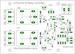
Fig.1
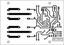
Fig .2
Fig. 3
Fig.4
Fig.5
Fig.6
Fig.7
Fig.8
Fig.9
Construction notes
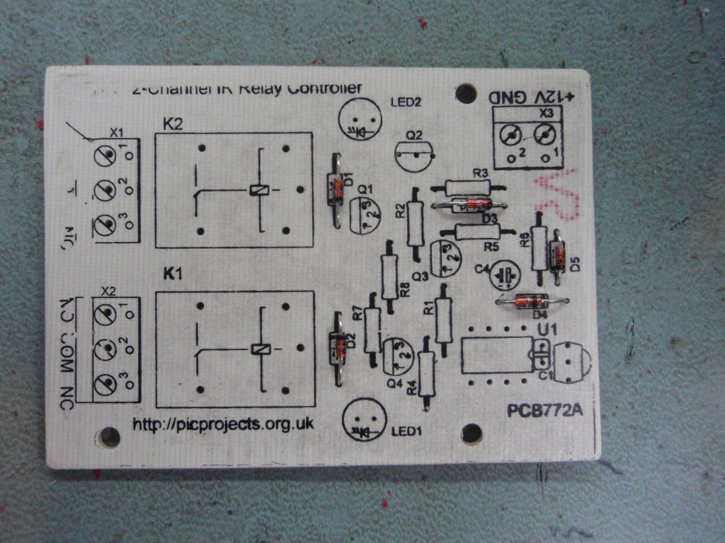
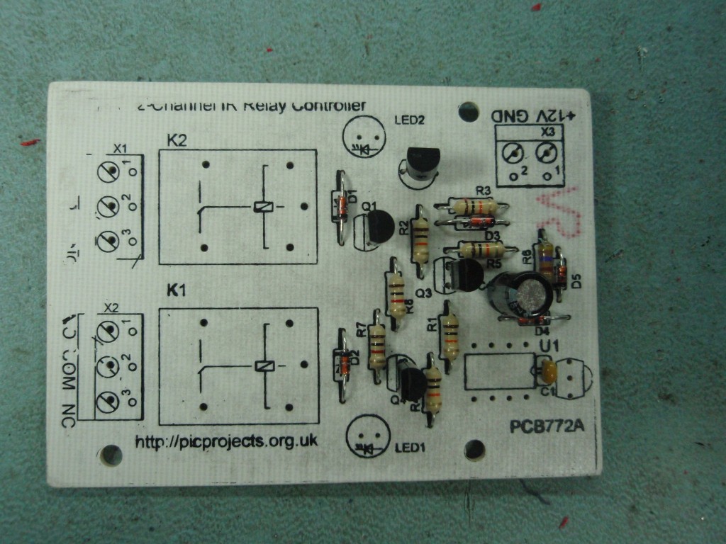
Fig 1. Install
the diodes. Make sure the black band marking on the diode
matches the overlay. Also make sure you don't get the 1N4148
and BZX55 zener diodes mixed up. They look virtually identical
so keep them separated and install them one at a time.
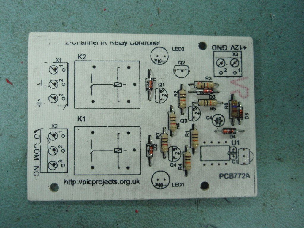
Fig 2. Install the
resistors. Doesn't matter which way round these go but it does
matter what values go where. Check the coloured bands 10K
and 1K Also
note: in these photos R6 is a 470R resistor
but after testing I decided to use a
680R
and that's what I've spec'd in the parts list.
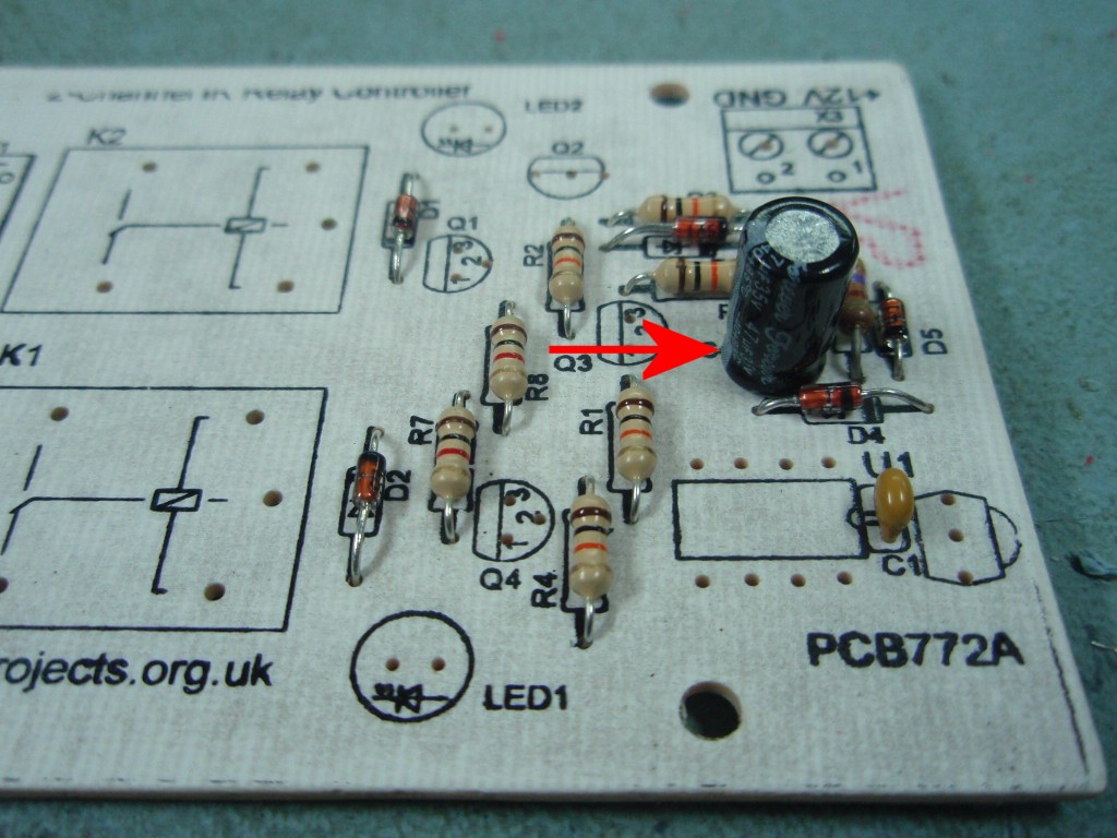
Fig 3. Now fit
C1 and C2. C2 is the 47uF capacitor and as it's a polarised part
it needs to be fitted the correct way round. One of the leads
will be shorter than the other. The short lead is the negative
terminal and should be fitted so it is on the side arrowed in the
photo (click on photo) C1 is the 100nF ceramic capacitor and
fits either way.
Fig 4. Next install the
four transistors. Q2 is a PNP transistor type BC327. The
other three are NPN type BC547 - don't get them mixed up. These need
fitting the correct way round, align the body of the part as shown
in the photos.
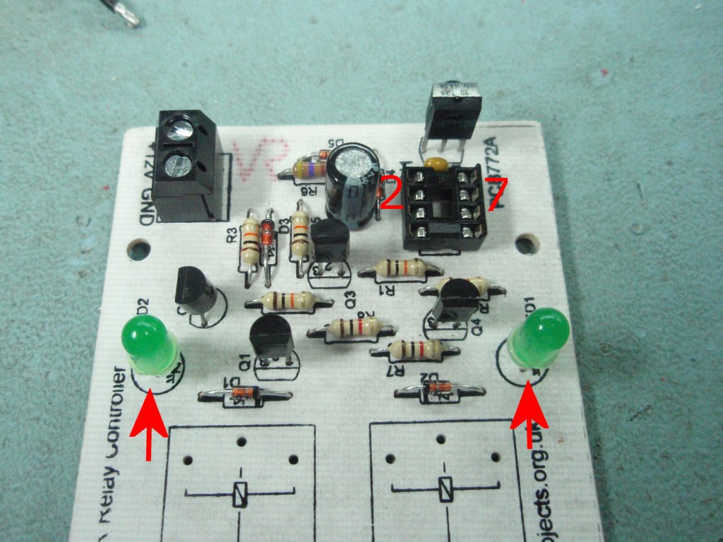
Fig 5. Finishing up
now, install the two LEDs. The LEDs have one lead shorter than
the other denoting the Cathode terminal. Fit the short lead into the hole nearest the relays
(also shown arrowed in photo). Install the 8 pin socket for U1
and the three screw terminal blocks.
At this point, before U1 and U2
are installed I recommend applying 12 volts to the power terminal.
Then using a voltmeter, measure the voltage between pins 2 (Vdd) and
7 (Vss) of
the U1 socket. It should measure 5.1 volts, if it doesn't find
out why and correct it before moving on.
Once you've tested the power,
disconnect the 12 volts supply - never work on a board with power
connected.
Program the PIC
If you haven't done this already
you need to program the PIC10F200 with the firmware at the bottom of this page before
fitting it to the board - it won't work until it is.
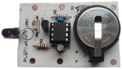
Fig 6. Now fit the
PIC10F200 U1 into the IC socket and the TSOP4838 U2, making sure they are both
fitted the correct way round. The PIC10F200 has a small indent
in the top of the package next to pin 1
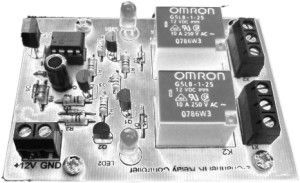
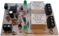
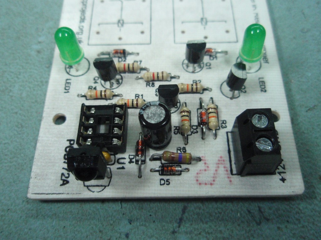
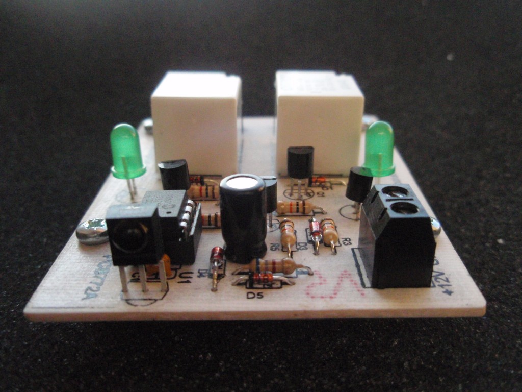
Fig 7/8/9. This is the
completed board with relays installed and U1 fitted in the socket.
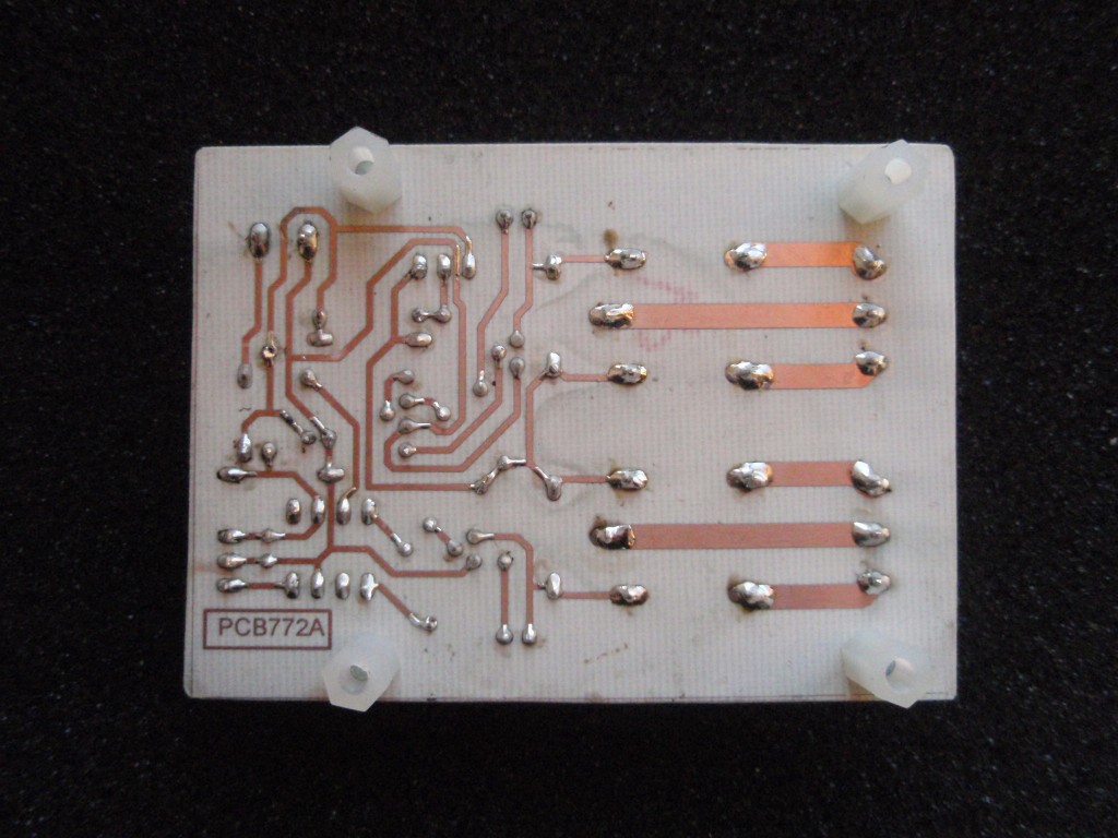
All done. Give the
board a once over checking for bad solder joints, bridges and
anything else that doesn't look right. If you're happy with the
construction, apply 12
volt power supply and recheck the 5.1 volts between pins 2 and 6 of
U1, if it's still correct then it's time to test with a remote
control.
Operating
The code in the download section is set for a Sony TV remote and
the following command buttons:
1 Toggle K1
2 Toggle K2
3
4 K1 off
5 K2 off
6
7 Momentary K1
8 Momentary K2
9 K1 & K2 on
0 K1 & K2 off
Toggle commands invert the
current state of the output
On / Off commands force
the output to that state
Momentary command turns
the output on only while the button is pressed, the output
turns off when the button is released.
You can use a one-for-all type
remote control set for a Sony TV, or take a look at the mini IR
remote control project here
designed to work with this relay board.
The buttons the commands respond to
can changed by editing the .asm file and reassembling the code.
Any commands you don't require or want deactived can be disabled by
setting the command code in the .asm file to 255. This is
documented in the .asm file.
Power Supply
The board needs a 12 volt DC
regulated supply. Current draw is about 80mA when
switching both relays on, in power save mode it drops to around
45mA and with both relays off it's under 10mA.
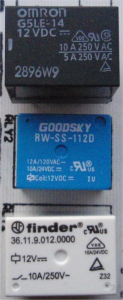
Relays
The relay
footprint is a standard size so the board can accommodate many
different makes / models. Just ensure that they are rated
for 12 volt operation and 360-400mW coil power.
Some that should
work are listed below:
Omron G5LB,
G5LE
Finder 3611.9012.0000
Goodsky RW/RWH series
Matsushita JS series
24 volt operation
If you want to use
this circuit with 24 volts relays it will work. Obviously
you will need to power it from a 24 volt supply not 12 volts.
You will also need to change the following parts:
D3
use BZX55-C9V1 9.1 volt zener diode
R6
use 1K8 0.25 watt 5% carbon film
R7, R8
use 3K9 0.25 watt 5% carbon film
C2 as
specified is rated for 25 volts so it should be okay, but
the 35 volt part would give more margin.
The HEX file is ready to
program straight into the PIC. The asm file is the
source code which you can modify and reassemble to work with
different SIRC device and command codes, or just view to see how it
works. If you need to reassemble the code for different
device/commands the 'Quick
Guide to MPLAB' may be helpful
Not got a
programmer? Buy a pre-programmed PIC for this project from
the online store
Editing the code for different
SIRC device/command codes
SIRC data is split into a
device word and a command word. Some of the codes
used with 12-bit SIRC are shown below, this list is not
exhaustive. Also be aware that there are 15-bit and
20-bit versions of SIRC. The firmware presented here does
not support decoding of the 15 or 20-bit versions.
Device
Type
1
TV
2
VCR 1
3
VCR 2
6
Laser Disc Unit
12
Surround Sound
16
Cassette deck /
Tuner
17
CD Player
18
Equalizer
Command
Function
0
Digit key 1
1
Digit key 2
2
Digit key 3
3
Digit key 4
4
Digit key 5
5
Digit key 6
6
Digit key 7
7
Digit key 8
8
Digit key 9
9
Digit key 0
16
Channel +
17
Channel -
18
Volume +
19
Volume -
20
Mute
21
Power
22
Reset
23
Audio Mode
24
Contrast +
25
Contrast -
26
Colour +
27
Colour -
30
Brightness +
31
Brightness -
38
Balance Left
39
Balance Right
47
Standby
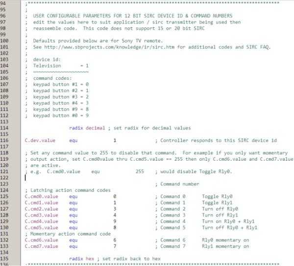
Open the .asm file in MPLAB and
locate the section of the code (see below) You can edit
these values to change the device ID and command codes the
controller will respond to. Once you have changed these
values you will need to assemble the code and then reprogram the
PIC10F200 with the resulting HEX file.
Setting a command code to 255
will disable that command. If you only want momentary
action on the outputs, change the value of C.cmd0.value thru
C.cmd5.value to 255. Then set C.cmd6.value and
C.cmd7.value to the command code for the button you want to
operate the output.