|
3-Switch
Mini IR Remote Control
for PIC10F200
|
 |
Description
|
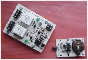
This project is a 3 button mini IR
remote control which transmits 12-bit SIRC IR signals as used by Sony remote controls.
It has been designed to work with both the
2-channel relay driver board
and 3-channel relay driver board
projects
also on this website.
The board uses Microchip's
low cost PIC10F200 microcontroller along with a handful of easy
to find components making it very cheap to construct. Everything you
need to know to build this project, including the firmware code is right here on the project
page.
|
 |
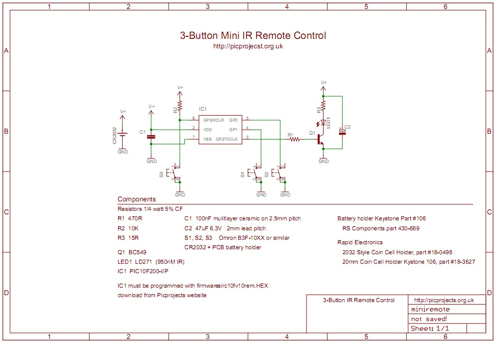
Schematic
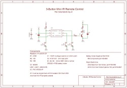
Download
schematic in PDF

Circuit Description
The circuit is very simple.
IC1 is a PIC10F200 microcontroller programmed with firmware to
generate a 40Khz carrier modulated with SIRC formatted data.
The three switches are each assigned a different command code
that the firmware will transmit via the IR LED when the switch
button is pressed. The whole unit is powered from a CR2032
3 volt lithium coin cell. When no button is pressed the
microcontroller goes to sleep where it consumes around 100nA
(0.1μA). If left unused the battery should last for many
years.
When a button is pressed the
microcontroller wakes and sends a SIRC device/command sequence
by driving transistor Q1 which in turn operates LED1, a 950nM
Infra Red LED. The transistor is used to drive around
100mA through LED1 giving a range of 7 or 8 metres.
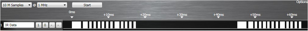
The SIRC data is sent in a
burst repeated every 45mS while the switch remains pressed.
The signal modulates a 40Khz carrier with a 24% duty cycle.
In the screen shot below you can see the data bursts (top) and
the 40Khz carrier (bottom)
This images shows the 2.4mS start burst, followed by a 1.2mS burst, then six 600μS
bursts (the command code 0000001 sent LSB first), then
another 1.2mS burst followed by four 600μS bursts
(device id 00001 again sent LSB first)
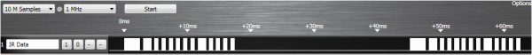
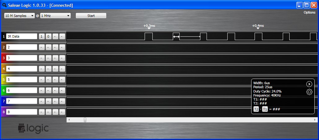
The screenshot below shows the
40Khz carrier with a 24% duty cycle
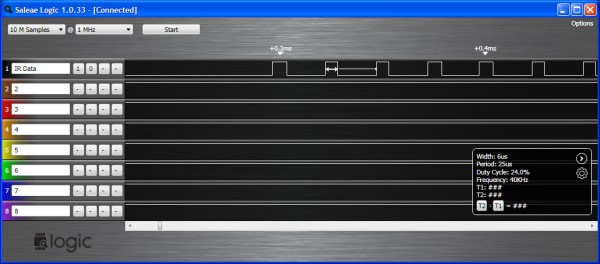
screenshots
above made with a
Saleae USB 8 channel logic analyzer for mac, PC or linux
For more information on the
SIRC infrared protocol see:
PCB Layout
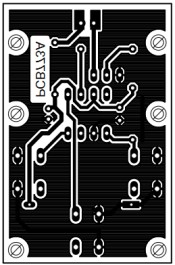
Download PCB
artwork in PDF
Download PCB
overlay in PDF
Suggested hole drill sizes:
- Mounting holes drill at
3mm
- Switches drill at
1.1mm
- IC1 and Battery holder drill at 0.85mm
- everything else drill at
0.75mm
Component List
You can buy all the parts
needed to build this project from most component suppliers world
wide. In the UK you can get everything from Rapid Online and
I've included a parts list with their part numbers below.

All
Rapid parts/descriptions correct at 07 February 2010. You should
check part# and descriptions are correct when ordering in case
I've made a mistake transferring them onto this page.
|
Component |
Description |
Part # |
| R1
* |
PACK 100 470R 0.25W CF
RESISTOR (RC)
|
62-0362 |
R2
* |
PACK 100 10K 0.25W CF RESISTOR (RC)
Not Required |
62-0394
|
| R3
* |
PACK 100 10R 0.25W CF
RESISTOR (RC)
|
62-0326 |
| C1 |
100N 2.5MM Y5V
DIELEC.CERAMIC (RC) |
08-0275
|
| C2 |
47U 16V 105 DEG.RADIAL
ELECT. (RC) |
11-1105
|
| Q1,3,4 |
BC549B TO92 30V
TRANSISTOR CDIL (RC) |
81-0068
|
| LED1 |
LD274-3 GAAS EMITTER
(RC) |
58-0442
|
| IC1 |
PIC10F200-I/PG
MICROCONTROLLER (RC) |
73-1952
|
| S1,S2,S3 |
TACTILE
SWITCH 6X6MM HEIGHT 7MM (RC) |
78-0622 |
| socket for U1 |
8 PIN 0.3IN TURNED PIN
SOCKET(RC) |
22-1720
|
| Battery holder |
2032 Style Coin Cell
Holder |
18-0498 |
Parts List Notes
*
All the resistors are
supplied in packs of 100 so only order 1 pack of each.
R2 is not required since the
10F series PIC has an internal pull-up on the GP3 input. (thanks
to Mike McLaren for pointing that out)
Not got a
programmer? Buy a pre-programmed PIC for this project from
the online store
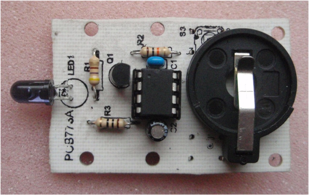
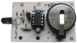
Construction
Photos
Construction is very
straightforward however, before you start please read
through this section so you know what to do, the photo's are
clickable to get a 1024x768 detailed version.
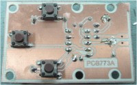
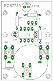
Fig.1 |
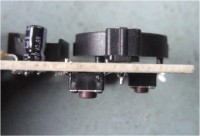
Fig .2 |
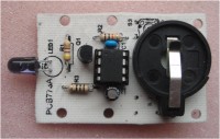
Fig. 3 |
| |
|
|
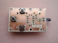
Fig.4 |
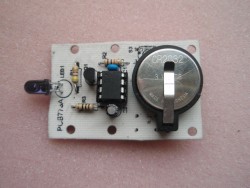
Fig.5 |
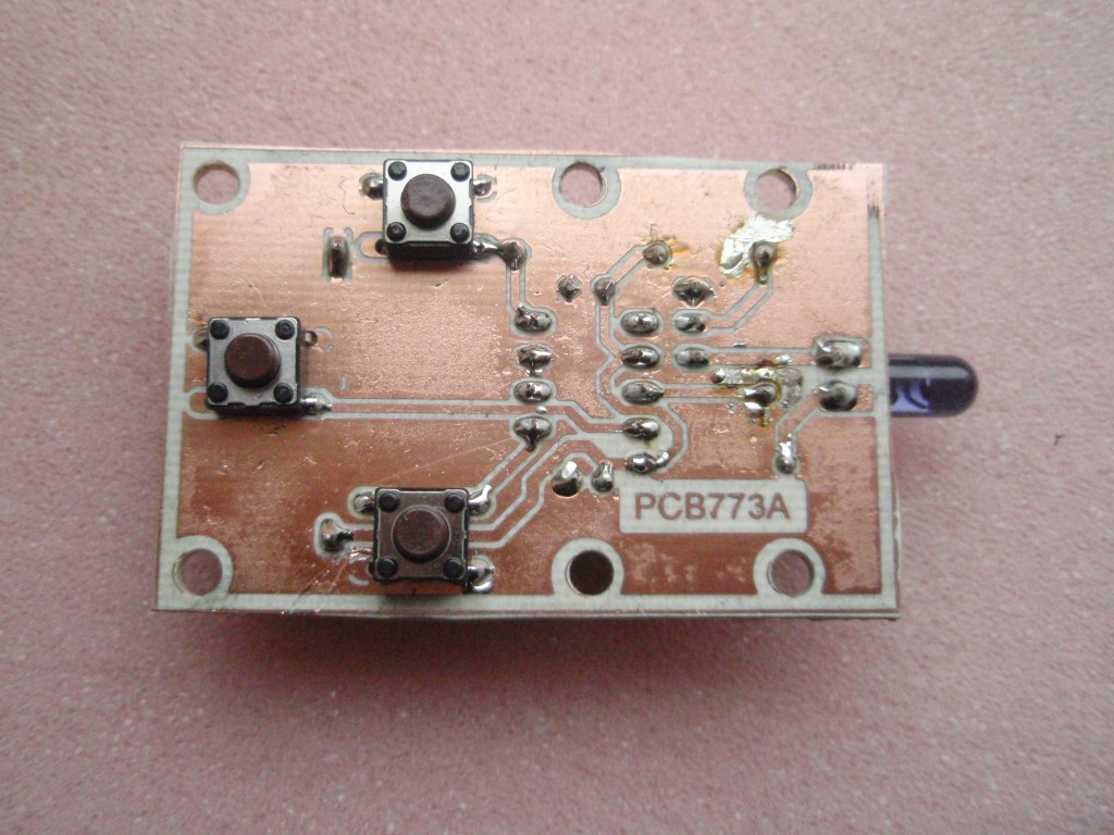
Construction notes
Fig 1. Install
the three switches on the copper side of the PCB.
 If you don't want to use all three switches, for example if you just
need a two switch remote control, simply don't fit the switch.
The firmware doesn't know or care if the switch is present unless it
is pressed.
If you don't want to use all three switches, for example if you just
need a two switch remote control, simply don't fit the switch.
The firmware doesn't know or care if the switch is present unless it
is pressed.
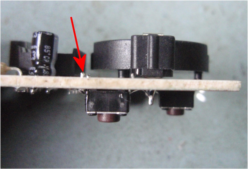
Fig 2. Before
fitting the battery holder, trim the ends of the switch leads that
protrude on the component side. If you don't do this the
battery holder won't fit against the PCB correctly.
Fig 3. There are
very few components used. Make sure to fit transistor Q1 the
correct way round and also capacitor C2. One of the wire leads
on C2 is shorter than the other. This is the negative terminal
and should be installed so it is on the side nearest the battery.
Resistors are R1 - 470R
 , R3 - 10R , R3 - 10R

R2 is not required since the 10F series PIC has an internal pull-up
on the GP3 input. (thanks to Mike McLaren for pointing that out)
Program the PIC
If you haven't done this already
you need to program the PIC10F200 with the firmware at the bottom of this page before
fitting it to the board - it won't work until it is.
The PIC10F200 has a small indent in
the top of the package next to pin 1, it should be fitted with this
towards C1
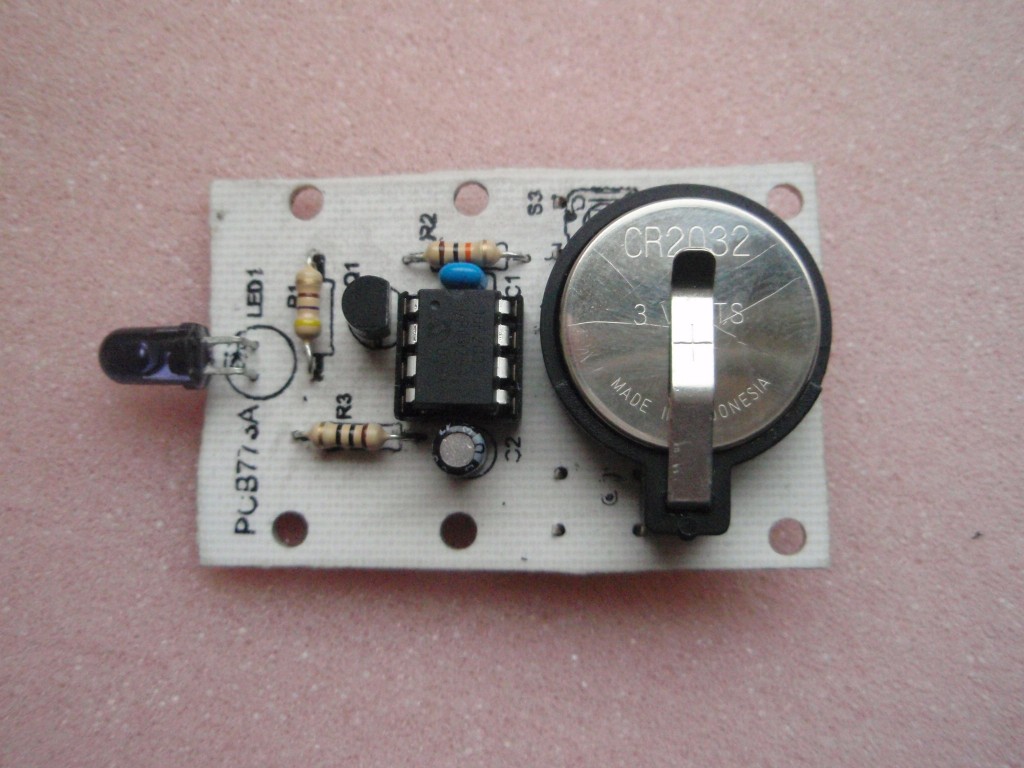
Fig 4. Make sure all the
solder joints are good and there are no bridges. Particular care is
needed since the board uses a ground plane so it is very easy to
accidently bridge across this.
Fig 5. Once the board
is assembled fit the battery
At this point using a voltmeter, measure the voltage between pins 2 (Vdd) and
7 (Vss) of
IC1. It should measure about 3 volts, if it doesn't, remove
the battery, then find
out why and correct it before moving on.
Operating
The code in the download section is set to operate the
2-Channel Relay Control board project.
The switches operate the relays as shown.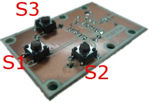
- S1 Relay K1 & K2 off
- S2 Toggle Relay K2
- S3 Toggle Relay K1
- Toggle commands invert the
current state of the output.
- On / Off commands force
the output to that state.
The device id and command codes
sent
can changed by editing the .asm file and reassembling the code. This
is described in the firmware section below.
Firmware
The HEX file is ready to
program straight into the PIC. The asm file is the
source code which you can modify and reassemble to work with
different SIRC device and command codes, or just view to see how it
works. If you need to reassemble the code for different
device/commands the 'Quick
Guide to MPLAB' may be helpful
Not got a
programmer? Buy a pre-programmed PIC for this project from
the online store
|
Description |
Filename |
Download link |
| Source
code for 10F200 |
sirc10fv10rem.asm |
 download
 |
HEX file
ready to program into the PIC
|
sirc10fv10rem.HEX 07/02/2010 |
download
checksum 0x4969 |
Editing the code for different
SIRC device/command codes
SIRC data is split into a
device word and a command word. Some of the codes
used with 12-bit SIRC are shown below, this list is not
exhaustive. Also be aware that there are 15-bit and
20-bit versions of SIRC. The firmware presented here does
not support transmission of the 15 or 20-bit versions.
|
Device |
Type |
| 1 |
TV |
| 2 |
VCR 1 |
| 3 |
VCR 2 |
| 6 |
Laser Disc Unit |
| 12 |
Surround Sound |
| 16 |
Cassette deck /
Tuner |
| 17 |
CD Player |
| 18 |
Equalizer |
|
|
|
Command |
Function |
| 0 |
Digit key 1 |
| 1 |
Digit key 2 |
| 2 |
Digit key 3 |
| 3 |
Digit key 4 |
| 4 |
Digit key 5 |
| 5 |
Digit key 6 |
| 6 |
Digit key 7 |
| 7 |
Digit key 8 |
| 8 |
Digit key 9 |
| 9 |
Digit key 0 |
| 16 |
Channel + |
| 17 |
Channel - |
| 18 |
Volume + |
| 19 |
Volume - |
| 20 |
Mute |
| 21 |
Power |
| 22 |
Reset |
| 23 |
Audio Mode |
| 24 |
Contrast + |
| 25 |
Contrast - |
| 26 |
Colour + |
| 27 |
Colour - |
| 30 |
Brightness + |
| 31 |
Brightness - |
| 38 |
Balance Left |
| 39 |
Balance Right |
| 47 |
Standby |
|
Open the .asm file in MPLAB and
locate the section of the code (see below) You can edit
these values to change the device ID and command codes the
mini remote will transmit. Once you have changed these
values you will need to assemble the code and then reprogram the
PIC10F200 with the resulting HEX file.
If you are using the 2-Channel
Relay Board and want the switches to operate the relay outputs
in momentary mode rather than toggle mode, change the values of
C.cmd.S3 to .6 (for Relay K1) and C.cmd.S2 to .7 (for Relay K2)
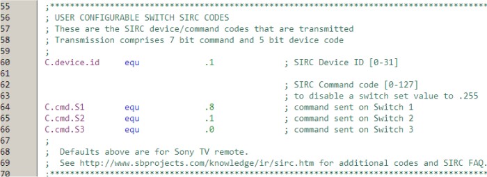
Setting a command code to 255
will disable that switch.
Contact us:
 |