This neat little circuit provides 8 LEDs
directly driven from the PIC along with a single mode control switch. The
firmware elsewhere on this page drives the LEDs with a
5 bit PWM signal providing each of the 8 LED channels with four
levels of intensity; off, dim, mid, bright.
A number of sequences are programmed into the firmware to
provide some interesting visual effects and chase sequences,
including the classic effect seen on the car in the
Knight Rider TV series.
The software has sequential, random and manual sequence run
modes and manual advance to the next sequence in any mode.
The selected sequence and mode are also saved to non-volatile
memory so it will always restart in the selected mode.
The design is kept simple with each
channel being directly driven from a PIC I/O pin. On board
LEDs allow operation to be monitored while the power MOSFETs
enable the board to control LED arrays and modules at currents
up to 2 amps.
You can use it with different
sized LEDs and mixed colours, as well as fewer than 8 LEDs.
As well as using it as a LED chaser it is great for adding
effects to toys and models. See FAQ
However, if you just want a
cool LED chaser without having to write any code, a ready
written LED chaser program including 34 chase effects with source code and
programmer ready HEX files is provided at the bottom of this page.
Power MOSFET
LED Chaser board testing with some 12 volt LED modules.
The LED modules shown I use for testing. I bought them
from an eBay seller from China in 2008
Power MOSFET
LED Chaser connected to LED Matrix signs. This runs from a
12 volt supply.
This LED
light suit uses the MOSFET LED Chaser project on this page to control the LEDs
in the suit - built by a customer using bespoke PCBs for
the LEDs which he designed and built himself.
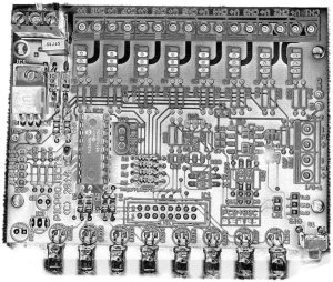
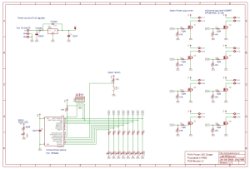
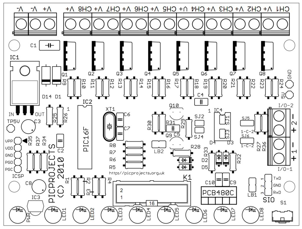
The heart of the LED chaser is
the PIC 16F628A microcontroller, IC2. The program that runs on this chip controls the LEDs
/ MOSFET drivers attached to the output port pins. Resistors R1 thru R8
limit the current through LED1 - LED8 to a safe level that
won't damage the PICs I/O ports or LEDs. These LEDs are
provided to monitor the main channel outputs, they can be
omitted them if this feature isn't needed.
Resistor R25
provides a pull-up for the input connected to switch S1.
R26 pulls up the PIC's MCLR reset signal during normal operation
while allowing the input to be raised to 12.5 volts during
in-circuit programming. The ICSP header provides connection for an ICSP programmer such as a PICkit2 making it easy to reprogram
the PIC without removing it from the PCB.
Power is supplied to the
circuit through the 3-way terminal block and must be smooth DC between 9 and 18 volts.
The PIC requires a precisely
controlled 5 volt supply and this is provided by IC1, a 7805
3-terminal, 5 volt regulator. Typical current drawn by the
circuit with all LEDs on is only around 100mA so the voltage
regulator doesn't require any additional heatsink. Capacitor C1
stabilizes the regulator. Capacitors C2 / C4 are used to
decouple the 5 volt power supply to the board. Diode D1 protects the circuit from
accidental reverse polarity of the input voltage. Diode
D14 protects the regulator and is only really needed if you will
be using the ICSP feature (doesn't hurt to fit it anyway)
The power output stage
comprises eight STP36NF06 N-Channel MOSFETs. These are
logic level devices with a low (logic level) gate threshold
making them suitable for driving from a PIC output. The
120R gate resistors limit the current during switching, the 47K
gate pull-down resistors prevent the MOSFETs from turning on
during power up and also from ESD (electro-static discharge).
Although rated at maximum of
30amps and 60 volts source/drain voltage, since the MOSFETs are
being used without any heatsink do not exceed 2 amps per
channel. In addition to this the connectors and PCB track
sizing also limit the maximum current per channel to 2 amps. DO NOT EXCEED 2 AMPS per CHANNEL
The 3-way terminal block
supplied with the kit is rated for 20 amps per terminal.
There are two terminals connected to V- (Ground). When
operating the board at maximum channel output currents it is
good practice to wire both inputs to ground.
Each channel can handle 3
amps however the combined channel current for the board
should not exceed 16 amps in total (2 amps per channel when
all channels are active
simultaneously)
The ICSP header
allows programming of the PIC while installed in the
circuit. It is only required if you intend to
connect a programmer to modify the sequences or code.
It is not supplied with the kit but is available as an
option.
The board itself requires
around 100mA to operate, however, the power supply used will
need to be specified to handle the total power required for
whatever LED modules / arrays are connected to the MOSFET
output channels.
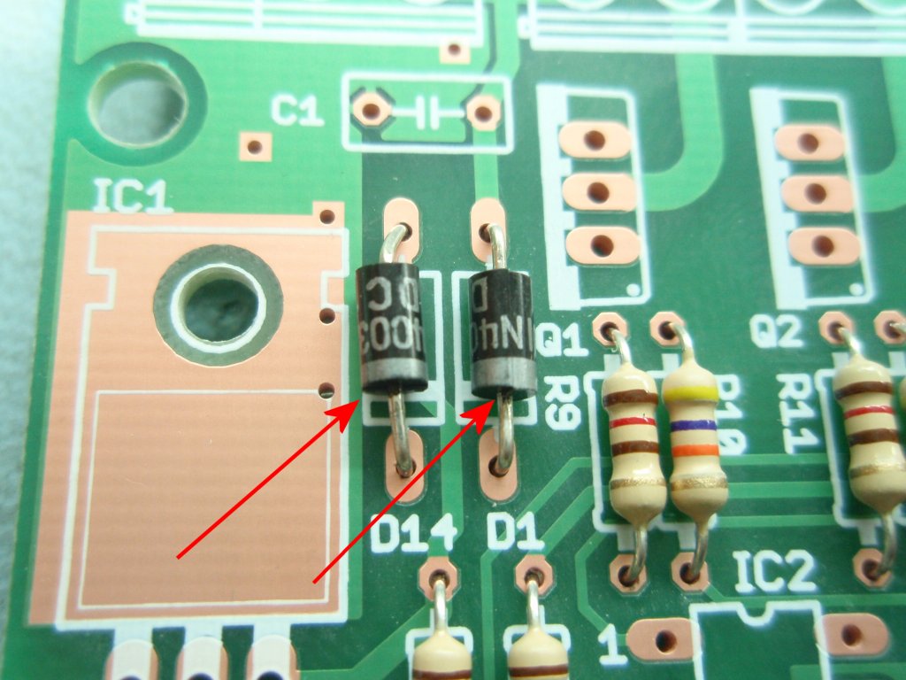
Diodes D1 and D14 are
shown as 1N4003. Any 1N400x series diode can be used
here.
S1 is a 6mm right angle
tactile switch, Omron B3F series.
Rapid Electronics part # 78-0140
cheaper alternative is Rapid Electronics part # 78-1154
IC1 is a 7805, 5 volt, 1
amp regulator IC.
For use in automotive applications, or where you need the
circuit to operate from input voltages down to 6 volts
replace IC1 with an LM2940CT-5 and install a 47µF/10volt
to C3
Rapid Electronics part # 82-0678 and part # 11-0815 or
11-1502
STP36NF06L MOSFETs are
logic-level N-channel devices. For use on this PCB
maximum current per channel is 2 amps (do not exceed this).
STP20NF06 can be used as an alternative.
Maximum current for the whole board should not exceed 16
amps.
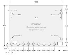
3-way and 2-way terminal blocks
are
5.08mm pitch but a 5mm part will also fit.
The PIC16F628A needs to be
programmed with the correct firmware (see
firmware section). If you bought the kit, this code is already programmed into
the supplied 16F628A.
C1 is 5mm polyester box
type
C2/C4 are 2.5mm radial lead
multilayer ceramic Y5V or X7R dielectric
Resistors are all 1/4
watt, 5% carbon film type.
The LED current limit
resistors R1-R8 are 330R. Don't use a lower value
resistor for these as it will affect the output voltage from
the PIC I/O pin reducing the voltage at the MOSFET gate.
All components used in this kit can be sourced from
Rapid
Electronics
Standard parts are used in
this project and should be easy to source from distributors
world wide.
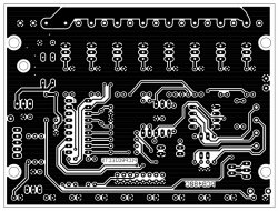
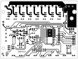
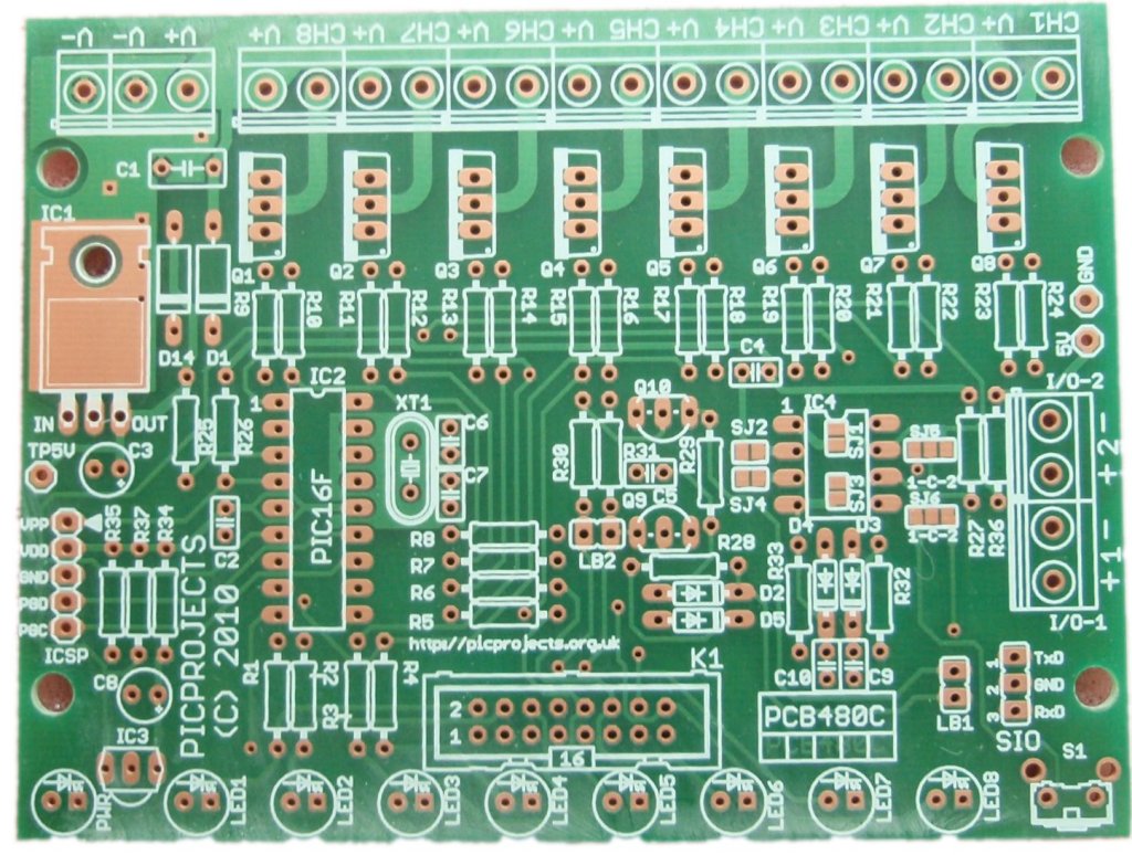
The PCB is available to buy
from the Picprojects online store. This a quality double
sided, thru-plated board with solder masks and component overlay
on FR4 board with RoHS compliant OSP finish to the copper.
The artwork is provided if you want to etch your own board,
however it is a double sided board and unless you can
thru-plate the holes it will be difficult to solder both sides
of some components such as the terminal blocks.
Illustrated guide to assembling the kit. Please
read through the whole of this section before starting
assembly and refer back to it during assembly.
click on the photo's for
1024 x 768 version
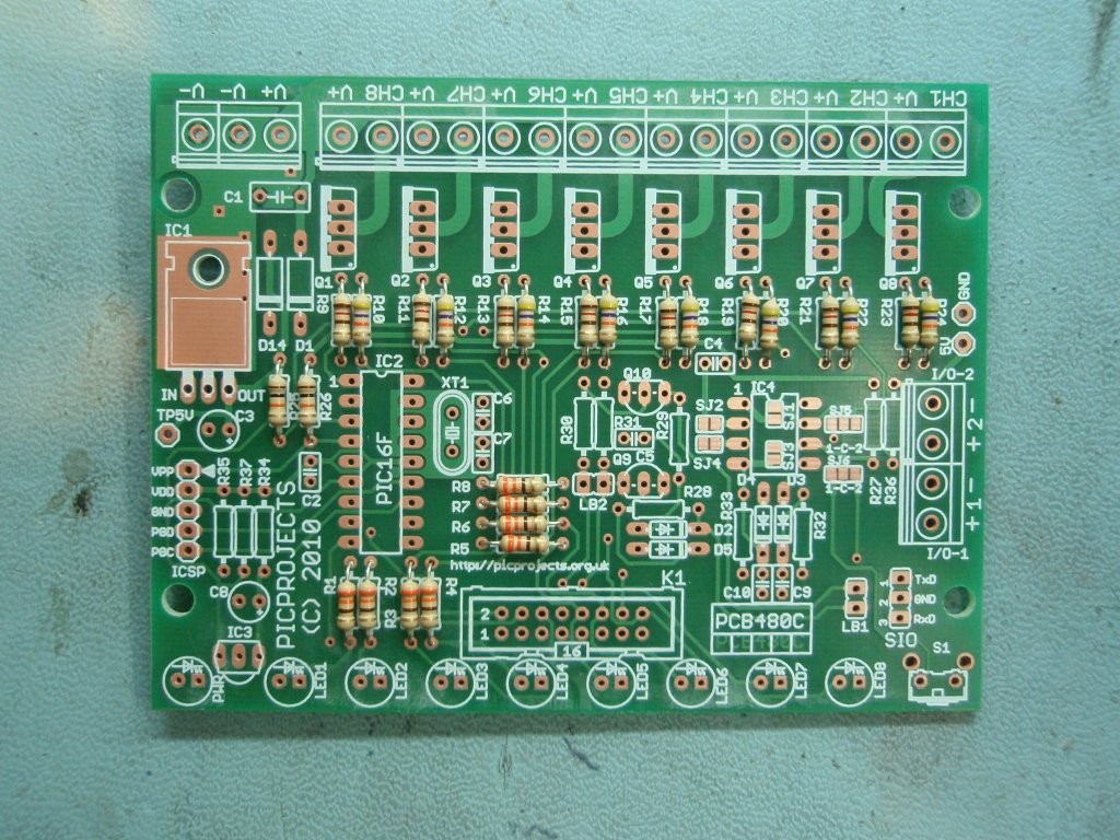
Step 1
Step 2
Step 3
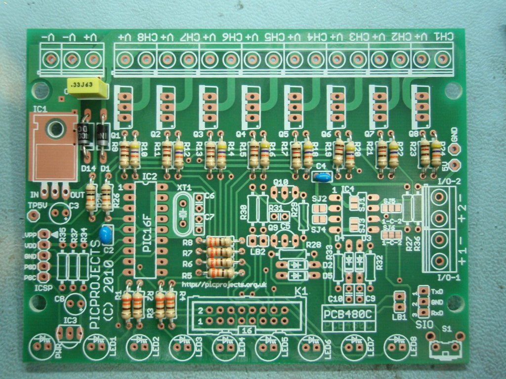
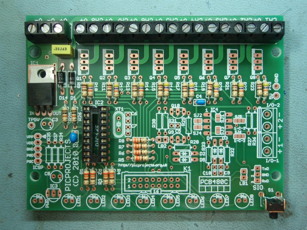
Step 1. Install the
resistors. The coloured bands denote the resistance value
as shown below. Fit the resistors into the correct
location on the PCB. It doesn't matter which way round the
are oriented.
Step 2. Fit the
two 1N4003 diodes. These have a silver band at one end of
the body and must be fitted the correct way round as shown.
Step 3. Install the
three
capacitors C1, C2 and C4. C1 is marked .33 J 63
(alternative part 470nF marked .47K63). Capacitors
C2 / C4 are marked 104.
It doesn't matter which way they are
oriented when fitting to the PCB
Step 4
Step 5
Step 6
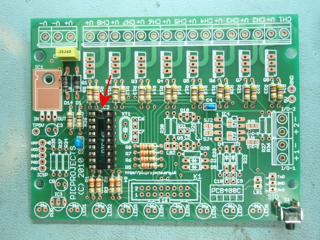
Step 4. Install
the socket for IC2. Note that it has a small indent at one
end, you should fit the socket with indent at the end arrowed in
the photo.
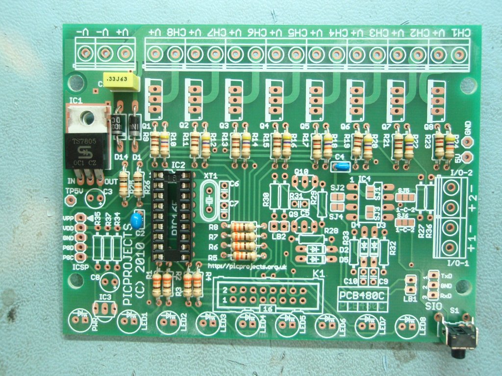
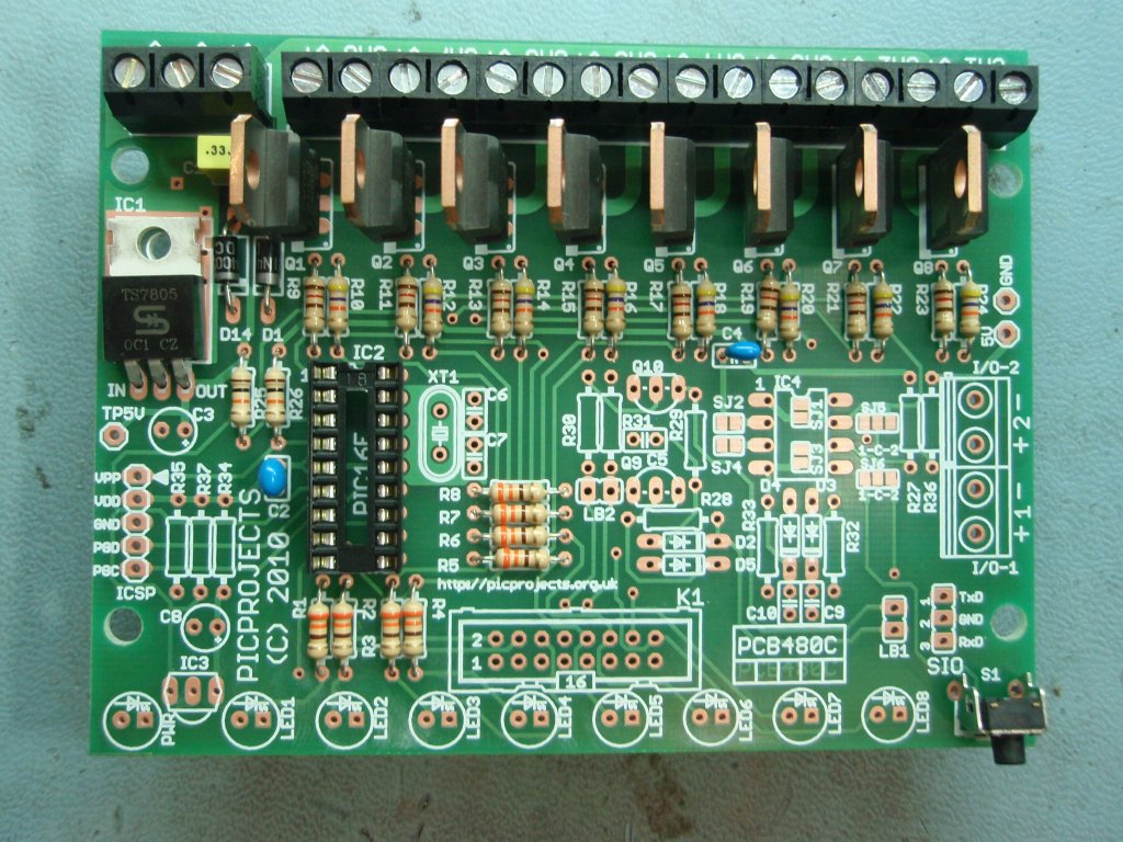
Step 5. Install
the 7805 voltage regulator to IC1. IC1 shares the same TO-220
standard packaging that the MOSFET driver transistors use.
IC1 will have the number 7805 laser-etched on the body.
The MOSFET transistors Q1-Q8 will have STP36NF06 (STP20NF06
alternative) on them.
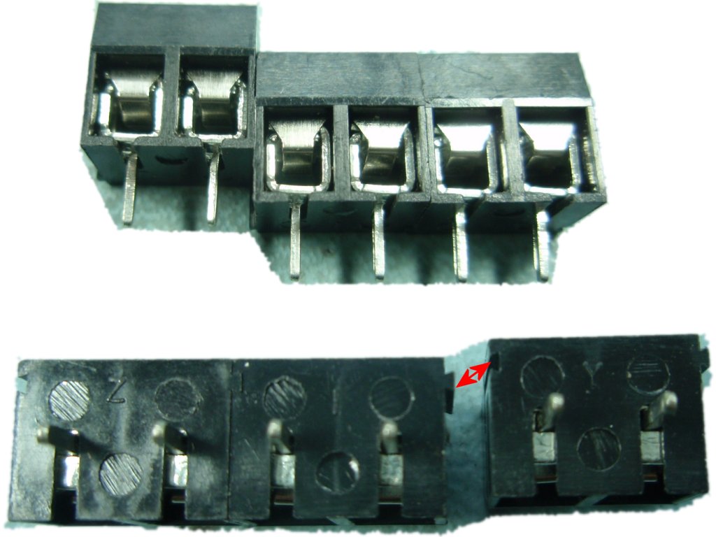
Step 6. Install
the eight 2-way terminal blocks. These are 'stackable'
connectors so slide them together using the dovetail on the side
of each block. It is easiest to make them up into two sets of 8
terminals before fitting to the PCB.
Step 7
Step 8
Step 9
Step 7. Once the
2-way terminal blocks have been connected to each other solder
them onto the PCB. Ensure they all fit snugly against the
PCB.
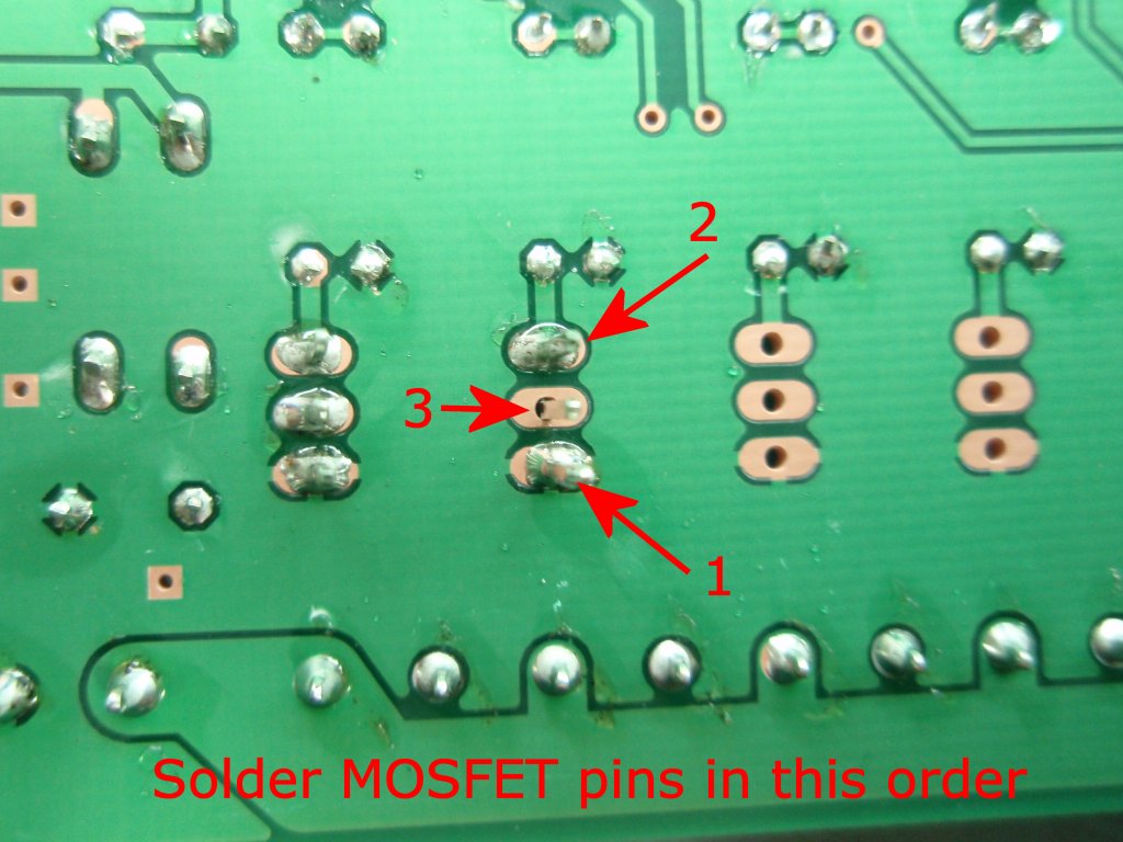
Step 8 / 9 Install the 8
MOSFETs to the PCB
Solder each MOSFET to the
PCB one at a time.
Ensure you have it
positioned the correct way round as shown in Step 8 photo.
Solder the pins of each
MOSFET in the order shown in Step 9 photo
MOSFETs
are static sensitive devices. Don't handle them
until you are ready to fit them to the PCB. Don't
touch the pins, handle the body only. Take anti-static
precautions
Step 10
Step 11
Step 12
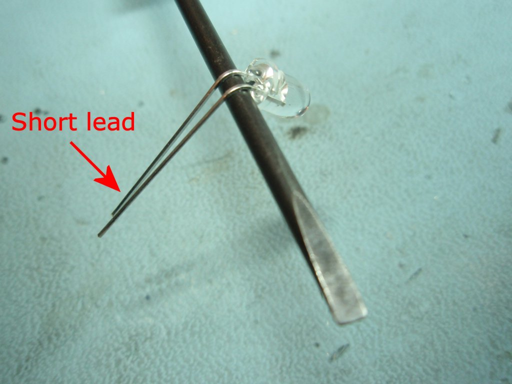
Step 10. When fitting
the monitor LEDs to the PCB use a thin screwdriver to bend the
leads of the LED around through 90o in a curve. One lead of the LED is shorter than the other.
This indicates the Cathode terminal of the LED. Ensure it
is positioned as shown otherwise it will be in the wrong
position to fit the PCB.
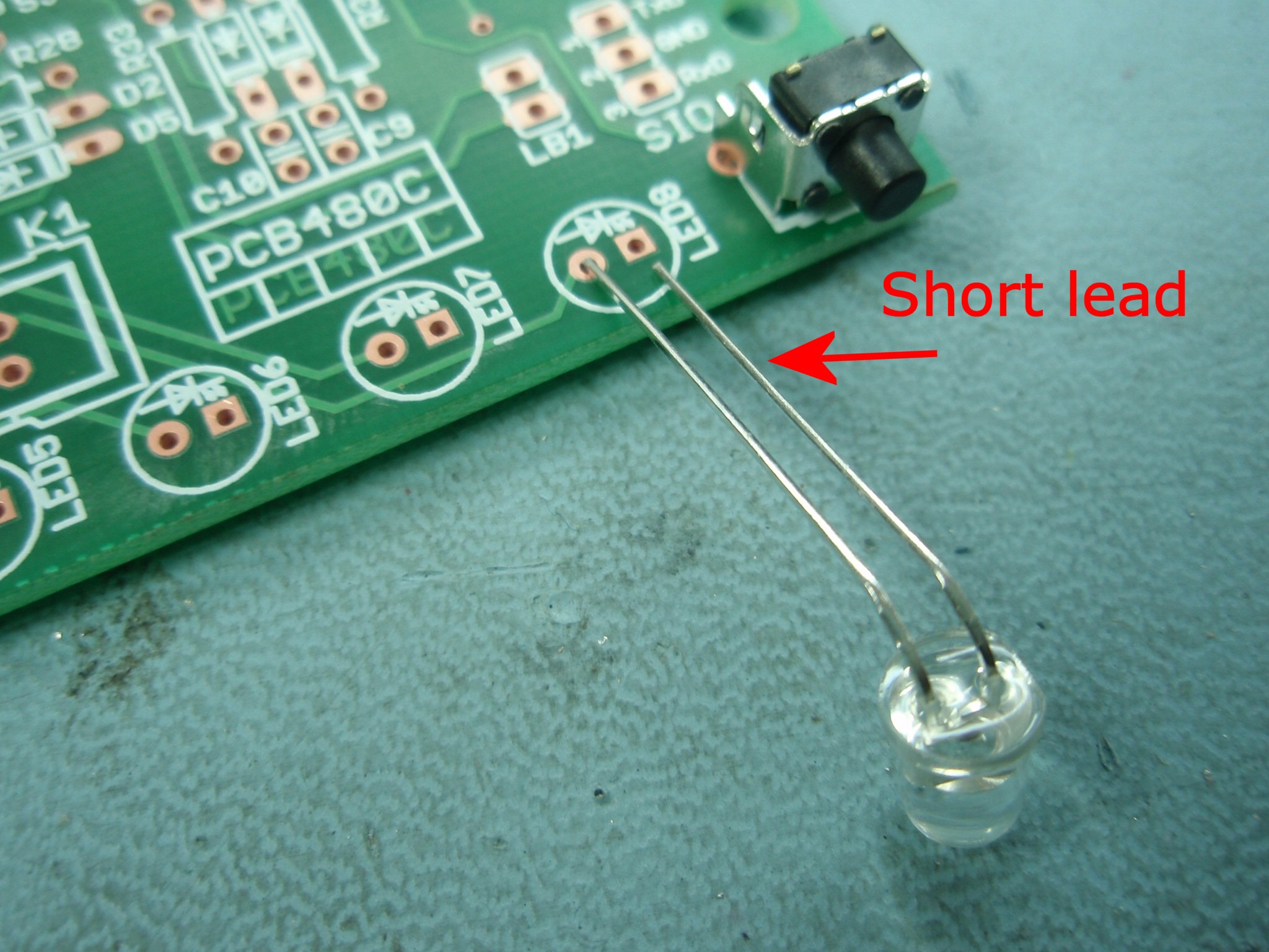
Step 11. Fit the
LEDs to the PCB with the short lead of each LED to the hole of
the square PCB pad.
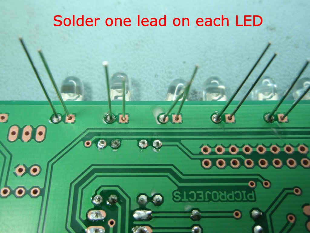
Step 12. Initially only
solder one lead of each LED as shown.
Step 13
Step 14
Step 15
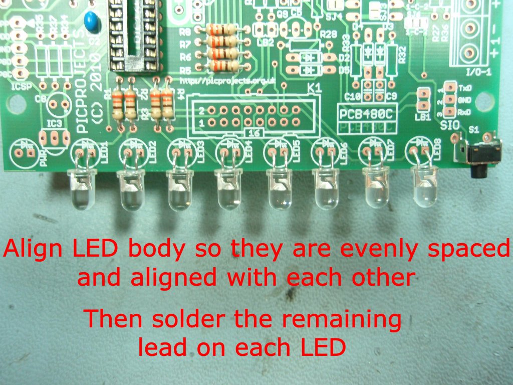
Step 13. Align the LEDs
so they are evenly spaced and when viewed horizontally form a
neat line. Once you have then aligned solder the remaining
leads of each LED.
At this point in the assembly.
Check the PCB to
make sure solder joints are neat and there are no
solder bridges between pins.
Make sure all
excess component leads have been neatly trimmed.
Clear the work
area of any component lead off-cuts, solder splashes
etc.
Step 14. Apply
power to the board. This should be 9-18 volts DC.
Connect the positive power lead to V+ on the 3-way terminal
block. Connect the negative or ground lead to either of
the V- connections on the 3-way terminal block.
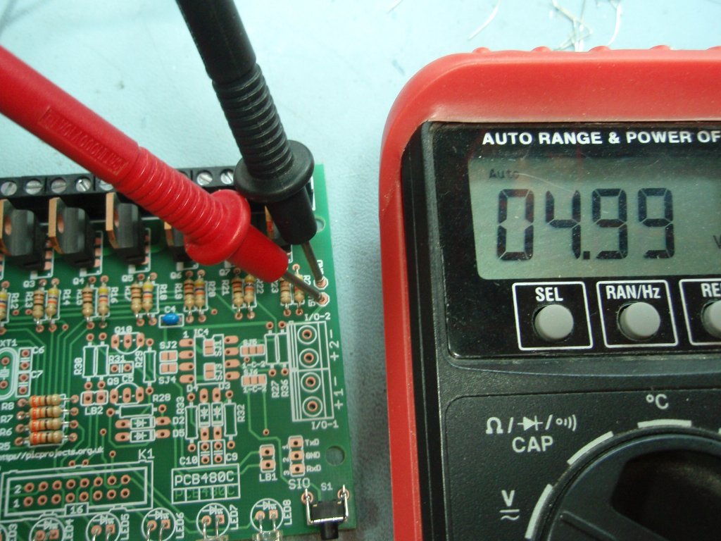
Now using a multimeter check
the 5 volt supply is present and of the correct voltage.
A reading between 4.75 and 5.25 volts is acceptable. There
is a Gnd and 5 volt test point on the right side of the PCB (see
Step 14 photo)
If the voltage is NOT within the acceptable range you must resolve the cause before
continuing.
Couple of points, should be obvious really but I'll
state it anyway:
Do not insert or
remove the IC2 when power is applied to the board.
Do not solder any
connections to or on the PCB while power is applied
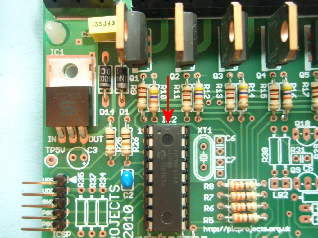
Step 15. Disconnect
the power from the board. Now you can fit the PIC
microcontroller into the IC2 socket. You will see a small
dot and indent at one end of the body. This should be
fitted so it is towards the end arrowed in the photo.
Step 16. Reconnect
power and turn on, the PCB mounted monitor LEDs should now start to run the
sequencer patterns.
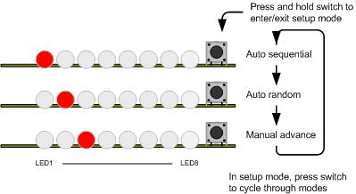
Press and hold S1 to enter
setup mode.
Press S1 to cycle through
the 3 modes.
Press and hold S1 to exit
setup mode.
If everything is working
correctly, construction of the main control PCB is complete.
Each channel output on the
control board connects to a MOSFET. In simple terms a
MOSFET is just a fast electrical switch. With a mechanical
switch you operate it by turning the switch on and off with a
finger. With the MOSFET, the PIC microcontroller turns the
MOSFET on and off. Unlike a mechanical switch or relay it
can turn on and off 1000's of times/second.
When the MOSFET is switched on,
it connects the channel output to V- (ground). If
some type of LED array / module is connected between the channel
output and the V+ supply it will light when the MOSFET is turned
on by the microcontroller.
Output protection
There is no fused protection on
the control PCB therefore depending on your application you may
want to add this externally.
Since the power output channels
can switch anything from a few milliamps to 2 Amps and the type
of power supply used is going to vary according to the type of
load a particular application is driving it is not possible to
give specific advice on wiring, fuses and power supplies.
However some points to consider
are discussed in this section.
Firstly, ensure the wire
gauge used for connections is correctly sized for the
current it is expected to handle.
Consider that each channel is
only rated to 2 amps maximum. Since a fault will typically
occur in a single output channel using, for example, a single 16
amp fuse at the input will most probably result in damage to the
PCB copper track, MOSFET and wiring before the fuse blows.
Therefore it is advisable to use an individual fuse in-line with
each output particularly where the combined channel current for the
board will exceed around 5 amps.
Depending on the power supply
you are using it may already include adequate fault and overload
protection on the output.
You should be particularly
careful if using this controller in automotive applications
since a car battery can deliver 100's of amps which if not
correctly protected could result in serious damage and/or
fire.
A short circuit between
the MOSFET channel output and the positive +V power supply
will most likely damage or destroy the corresponding MOSFET,
particularly if a high current output power supply is in
use. Therefore pay particular attention to wiring of
the controller to the load to ensure all connections and
cables are correctly wired.
Please note that this is general
advise and you should ensure you design the cabling, power
supply and suitable over-current protection
for your specific application.
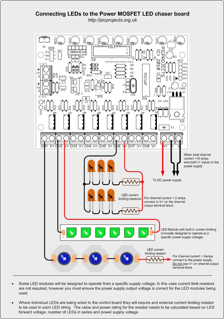
Examples of connecting to
the channel outputs
The diagram below shows how to
wire to the channel outputs of the control PCB.
Some LED module will be
designed to operate from a particular voltage, in this case they
don't need the in-line current limiting resistor since these
will already be built into the module itself. When using
this type of module you must ensure the input voltage to the
control PCB is correct for the LED modules being used.
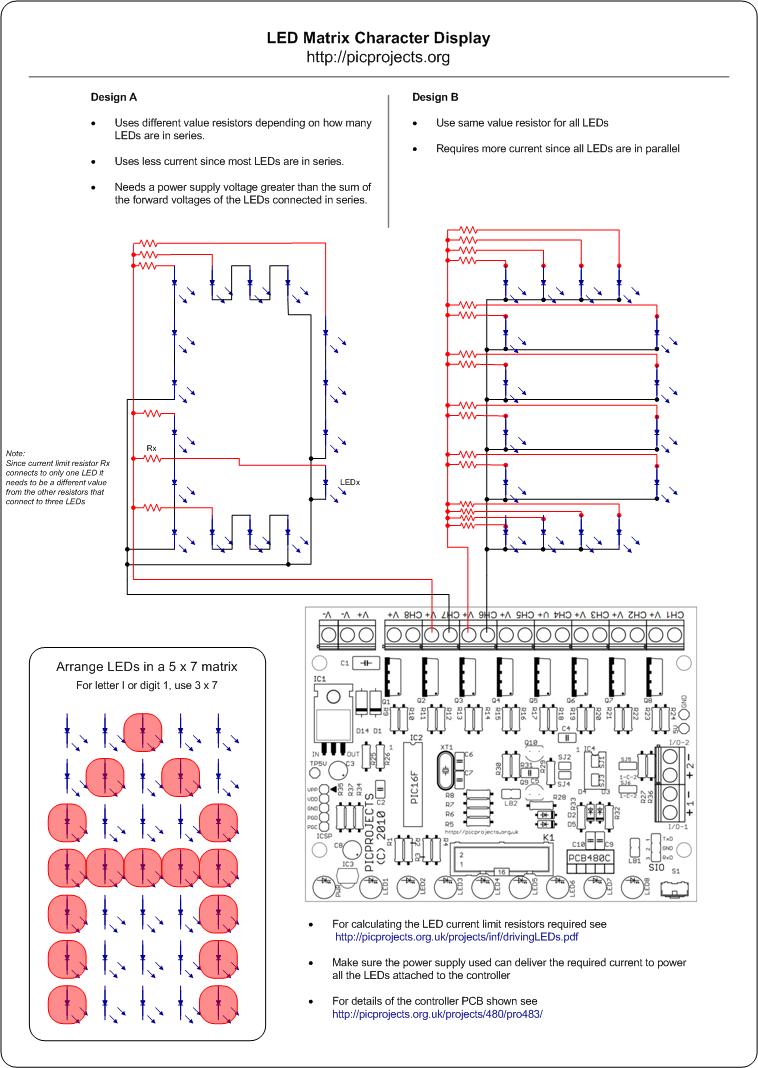
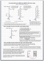
Where individual LEDs are used,
current limiting resistors must be included to avoid destroying
the LEDs. The value of the resistor required must be
calculated according to the characteristic of the LEDs being
used and power supply voltage.
The 'Driving LEDs' document
below explains how to calculate the resistors required.
You may also find the excellent LED Calculator app at
http://led.linear1.org/led.wiz very useful. The
schematics produced by the LED calculator app show the resistor
connected to the cathode or negative end of the LED strings. I
always show it connected to the anode or positive end. It
doesn't actually matter where it connects as long as it is
fitted.
Manual mode will run the
same sequence continually. When the switch is pressed it
will skip to the next sequence in program memory.
In auto-sequential mode,
the program runs through each sequence in program memory
until it reaches the end of all defined sequences at which
point it restarts from the first one.
In random mode the program
selects sequences randomly.
When the code is running in any
mode, a short press of the switch will make the controller skip
to the next sequence.
To enter setup mode, press and
hold the switch. Once it enters setup mode one of three
LEDs will light indicating the current run mode. A short
press of the switch cycles through the three modes. When the
desired run mode has been selected, press and hold the switch to
exit setup and return to run mode.
The current mode and selected
sequence are automatically saved to the PICs internal
non-volatile EEPROM memory 10 seconds after the last switch
press. When the LED chaser is next powered up it will load
and start running using the saved mode and sequence.
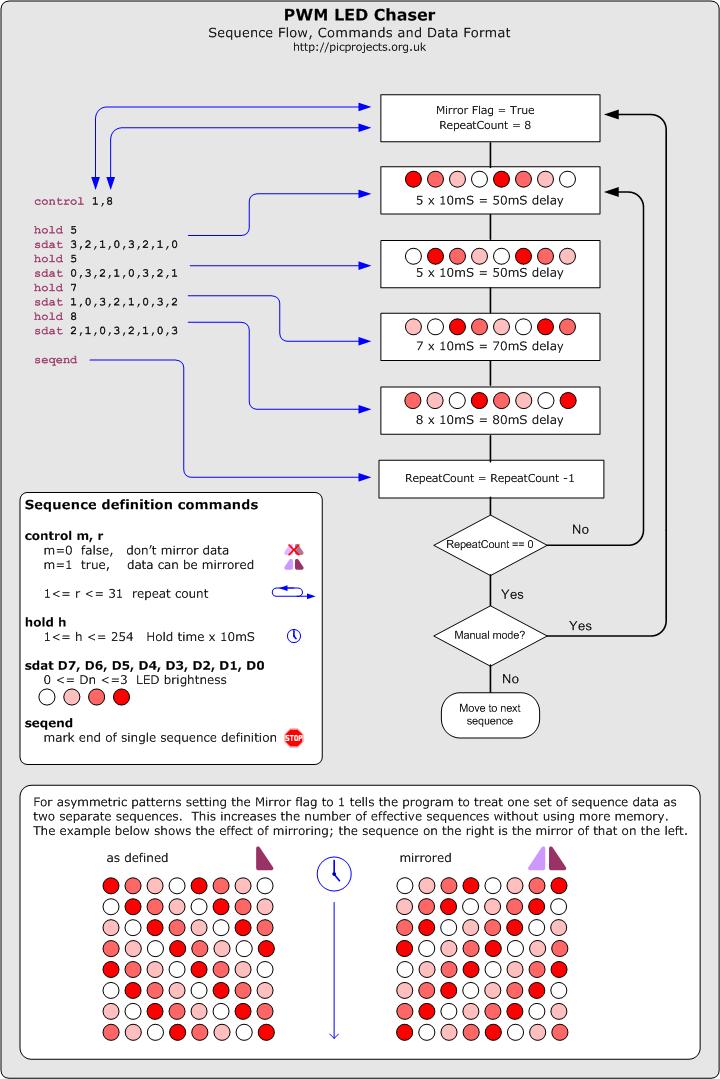
The data
used to create the sequences is held in a separate
include file. You can add, remove or edit this
data to create your own chaser sequences.
To make the creation of
the data file easier a set of macros have been defined
which are used to create the sequence data. This
is described in the
Sequence data flowchart
(also available
as a JPEG image right)
If you download the
source code and look at the file named
pro418v3_SeqData.inc you can see the data used in the
project. You might want to edit this file as a
starting point to create some sequences of your own.
Notes:
In manual mode,
when the repeat count reaches zero it will restart
the same sequence, to advance to the next sequence
press the switch.
In Random mode it
will the select a random sequence number to run. If
the Mirror flag is true for that sequence it will
also randomly choose to mirror the data or not.
In auto-sequential
mode if the Mirror flag is true it will run the
sequence and then repeat it with the data mirrored.
If you need a PIC Programmer I
strongly recommend the
Microchip PICKit 2,
this is available from suppliers world wide or direct from
Microchip. It's reasonably cheap to buy and reliable.
I have a couple of them and I wouldn't use anything else now.
Can you or
how can I make it run
more than 8 Channels?
This is probably the most
frequent of the frequently asked questions :-)
The project is an 8 Channel LED Chaser
and the firmware was written to work as an 8 Channel chaser.
There is no quick and easy
change to make it a 9, 12 or some other number of Channels.
If you need a chaser with more channels then this project is not
suitable for your needs.
Can I use
less than 8 LEDs?
Yes, since the sequences are
user definable you can create sequences that use less than 8
LEDs.
I only want
it to run one sequence, can it do that?
Since the current mode and
selected sequence are saved to NVRAM, it always powers up in the
last mode and running the last sequence. Therefore if you
select manual mode and the sequence required, it will run only
that sequence until you change it.
Can you add
a button or potentiometer to change the speed?
The sequences don't have a
speed as such, the data for each step in a sequences includes a
hold time which has to elapse before moving to the next step in
the sequence. This hold time is user defined and can be
different for each step in a sequence. The speed a
sequence runs at is therefore fixed in the data and there is no
option to speed up or slow down a sequence when it is running.
See Description of
Sequence Data
Can you
modify the code to run on a PIC type xyz?
If you
want to modify the source code it could be made to run on other PIC types, however we won't modify the code.