|
8
Channel PWM LED Chaser
for 16F628A and 16F88
|
 |
Description
This neat little circuit provides 8 LEDs
directly driven from the PIC along with a single mode control switch. The
firmware elsewhere on this page drives the LEDs with a
5 bit PWM signal providing each of the 8 LED channels with four
levels of intensity; off, dim, mid, bright.
A number of sequences are programmed into the firmware to
provide some interesting visual effects and chase sequences,
including the classic effect seen on the car in the
Knight Rider TV series.
The software has sequential, random and manual sequence run
modes and manual advance to the next sequence in any mode.
The selected sequence and mode are also saved to non-volatile
memory so it will always restart in the selected mode.
The design is deliberately
simple with each LED being directly driven from a PIC I/O pin.
This and the inclusion of an in-circuit programming header (ICSP)
make the circuit ideal for teaching/learning introductory PIC
assembly language programming.
You can use it with different
sized LEDs and mixed colours, as well as fewer than 8 LEDs.
As well as using it as a LED chaser it is great for adding
effects to toys and models. See FAQ
However, if you just want a
cool LED chaser without having to write any code, a ready
written LED chaser program including 34 chase effects with source code and
programmer ready HEX files is provided at the bottom of this page.
The circuit has been
constructed on a PCB but can easily be built on strip-board or a solderless breadboard.
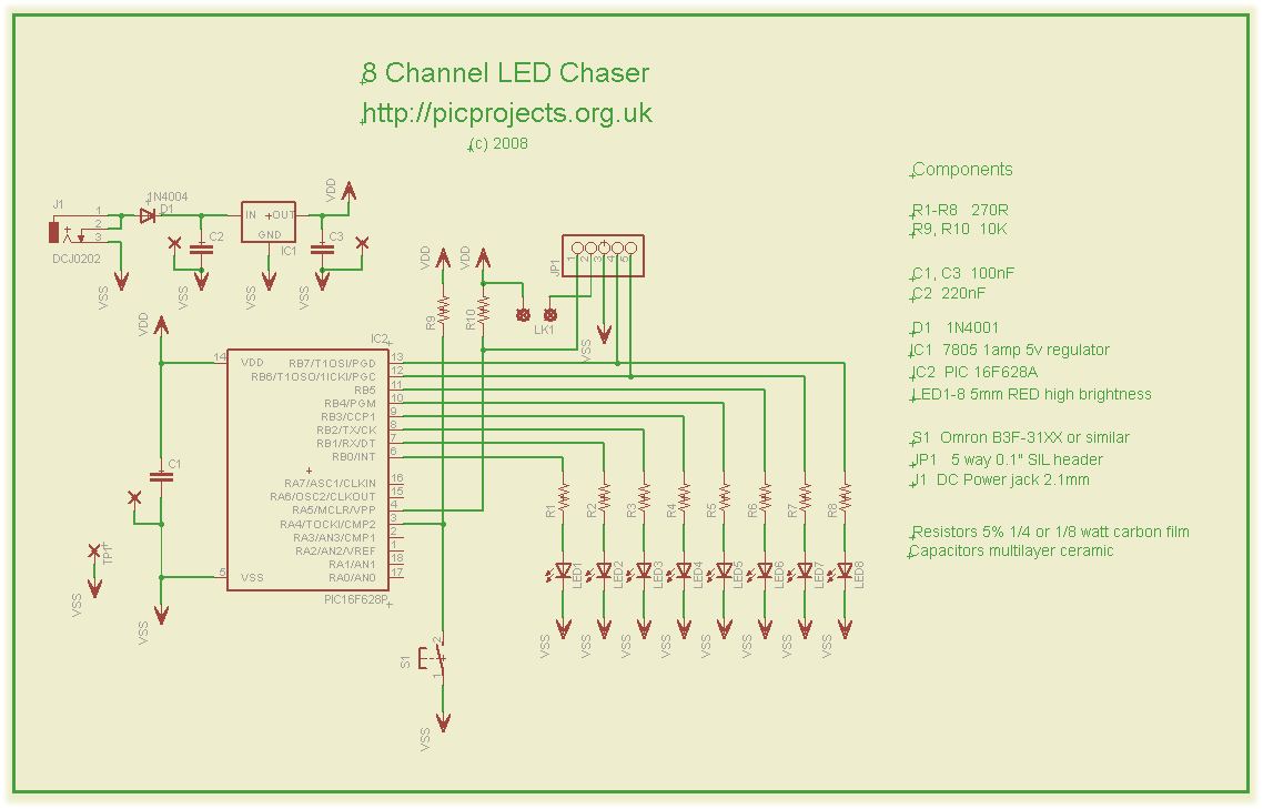
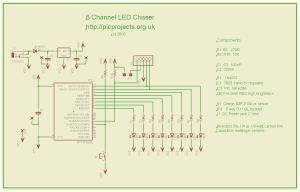
Schematic
Download
schematic in PDF

Circuit Description
The heart of the LED chaser is
the PIC 16F628A microcontroller, IC2. The program that runs on this chip controls the LEDs
attached to the output port pins. Resistors R1 thru R8
limit the current through LED1 - LED8 to a safe level that
won't damage the PICs I/O ports or LEDs. Resistor R9
provides a pull-up for the input connected to switch S1.
R10 pulls up the PIC's MCLR reset signal during normal operation
while allowing the input to be raised to 12.5 volts during
in-circuit programming. JP1 provides connection for an
ICSP programmer such as a PICkit2 making it easy to reprogram
the PIC without removing it from the PCB.
Capacitor C1 is used to
decouple the 5 volt power supply to the PIC. If you're building the
circuit on a breadboard or stripboard you should ensure it is
located close to the PICs Vdd connection (pin 14 ).
Power is supplied to the
circuit via J1 and must be smooth DC between 9 and 14 volts.
The PIC requires a precisely
controlled 5 volt supply and this is provided by IC1, a 7805
3-terminal, 5 volt regulator. Typical current drawn by the
circuit with all LEDs on is only around 100mA so the voltage
regulator doesn't require any additional heatsink. Capacitors C2 and C3
stabilize the regulator. Diode D1 protects the circuit from
accidental reverse polarity of the input voltage.
Notes:
- Capacitors C2/C3
stabilize the voltage regulator and may be
omitted for most applications, however the schematic shows
them and the PCB layout makes provision for them. If
you're unsure whether you will need them then it's best to
install them.
- The latest
high brightness LEDs are very bright even with 270R current
limiting resistors. However, if you do need to change these resistors
for some reason take into account the maximum current
that the PIC can source from an I/O port pin is 25mA, and
also be aware that the output voltage will drop as you
increase the load.
- If you install LEDs
that require a lower value series resistor you may find you
are unable to program the PIC in-circuit via the ICSP
header. This is because the I/O port pins on the PIC
that are used for In-Circuit Serial Programming are shared with the LEDs. The programmer may be unable to drive these
lines when lower value resistor are used. With the
270R resistors and PICKit2 programmer, In-Circuit
programming should work without problems.
- JP1 is an ICSP header
to allow programming of the PIC while installed in the
circuit. It is only required if you intend to
connect a programmer to modify the sequences or code.
It is not supplied with the kit.
Pin 2 of this header connects to the circuit's
5 volt supply via the link LK1. Since the circuit
provides an onboard 5 volt regulator, the circuit should be
powered from this and the link left open. Pin 1 of the ICSP
header JP1 is nearest the LEDs
- If you have an external
5V supply, you can omit D1, C2, C3 and IC1. You will
need to install wire links in place of D1, and between pins
1 and 3 (in-out) of IC1. The circuit will now work
from the external 5V supply. Be sure to connect it up
correctly because without D1 in place there is no reverse
polarity protection.
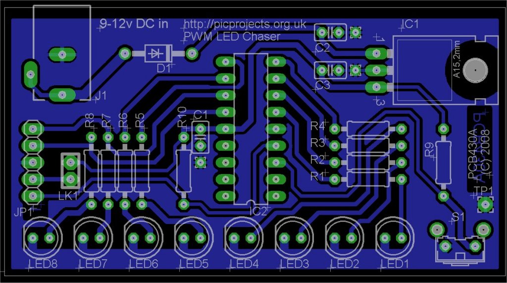
PCB Layout
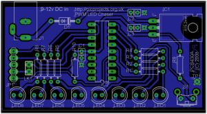
Download PCB
artwork in PDF
Download PCB
component overlay (JPG)
Component List
You can buy all the parts
needed to build this project from most component suppliers world
wide. In the UK you can get everything from Rapid Online and
I've included a parts list with their part numbers below.

All
Rapid parts/descriptions correct at 2-October-2008. You should
check part# and descriptions are correct when ordering in case
I've made a mistake transferring them onto this page.
Ordering parts from
Rapid?
Use the cut & paste quick order form on their
home page
with this list of
parts

| Component |
Description |
Part # |
| R1 - R8 (order 1
pack) |
PK 100 270R 0.25W CF
RESISTOR (RC) |
62-0356 |
| R9,R10 (order 1
pack) |
PACK 100 10K 0.25W CF
RESISTOR (RC) |
62-0394
|
| C1,C2 |
100N 2.5MM Y5V
DIELEC.CERAMIC (RC) |
08-0275
|
| C3 |
220N 5MM Y5V DIELECT.CERAMIC (RC) |
08-0280 |
| J1 |
2.1 PCB DC POWER
SOCKET (RC) |
20-0970 |
| socket for IC2 |
18 PIN 0.3IN TURNED
PIN SOCKET(RC) |
22-1723 |
| IC1 |
L7805CV +5V 1A VOLTAGE
REGULATOR (ST) RC |
47-3290 |
| IC2** |
PIC16F628A-I/P (RC)
|
73-3340 |
| D1 |
1N4001A 1A 50V
RECTIFIER DIODE (RC) |
47-3420 |
| LED1 - 8* (order 8) |
L-7113ID LED 5MM RED
DIFF 45MCD (RC) |
55-0155
|
| S1 |
5.85MM
RIGHT ANGLE TACT SWITCH (RC) |
78-1152 |
| JP1 |
5 W SINGLE
ROW PCB HEADER PLUG (RC) |
22-0510 |
| Power supply
*** |
9V 600MA MINI PLUGTOP
SW MODE PSU RC |
85-2957 |
Parts List Notes
* You can use almost any type of 5mm LEDs
of any colour with this circuit.
** PIC16F628A will need
programming (see below)
***
If you don't have a power supply, this one should be
suitable.
PIC Programmer
You can also buy the PICkit2 starter kit from Rapid, part #
97-0101
Construction notes:
click on the photo's for
large version

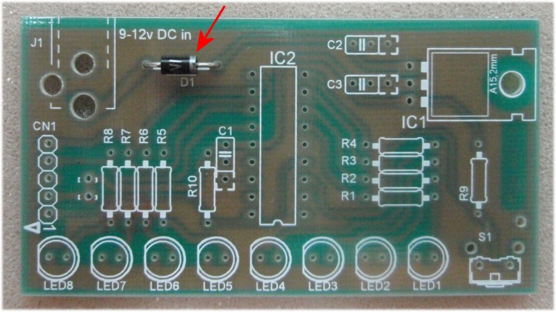
Fig.1 |
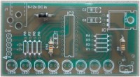
Fig .2 |
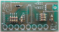
Fig. 3
|
|
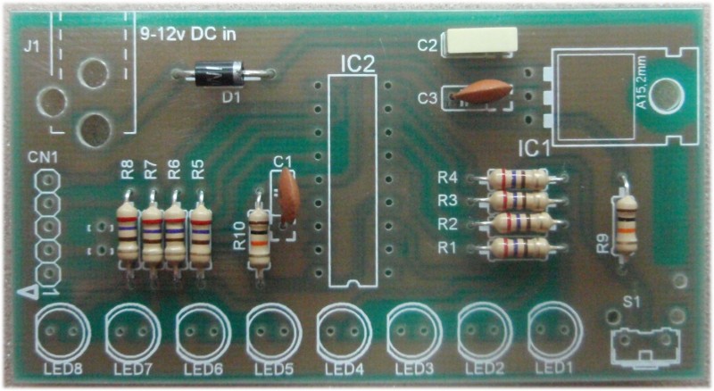
In Fig 1.
Fit diode D1. Note the silver band on the body of the
diode. Ensure it is fitted the correct way round so it
matches the PCB overlay.
Fig 2. Fit the
two 10K
resistors (these have Brown, Black, Orange Gold bands on
the body)
Fig 3. Fit the eight
270R
resistors (these have Red, Violet, Brown, Gold bands on
the body)
|
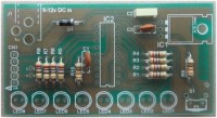
Fig.4 |

Fig.5 |
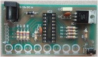
Fig.6
|
|
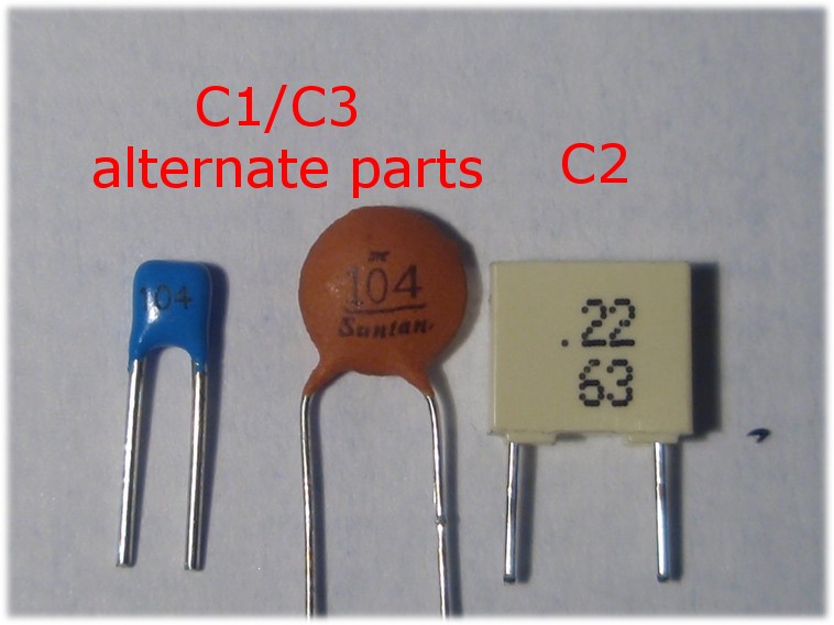
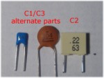
Fig 4. Fit
the three capacitors, C1, C2, C3.
If you're assembling
from the kit C1 and C3 are the same value, but can be
one of two types and will be marked '104'
C2 is marked '.22' and
is a white rectangular part.
|
 |
|
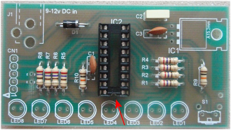
Fig 5. Fit the
socket for IC2. Note the notch in one end of the
socket. It should be fitted so the notch is in the
same direction as the marking on the PCB overlay
Fig 6. Now fit
the voltage regulator IC1, the switch and the DC power
jack
|
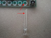
Fig.7 |

Fig.8 |
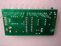
Fig.9
|
|
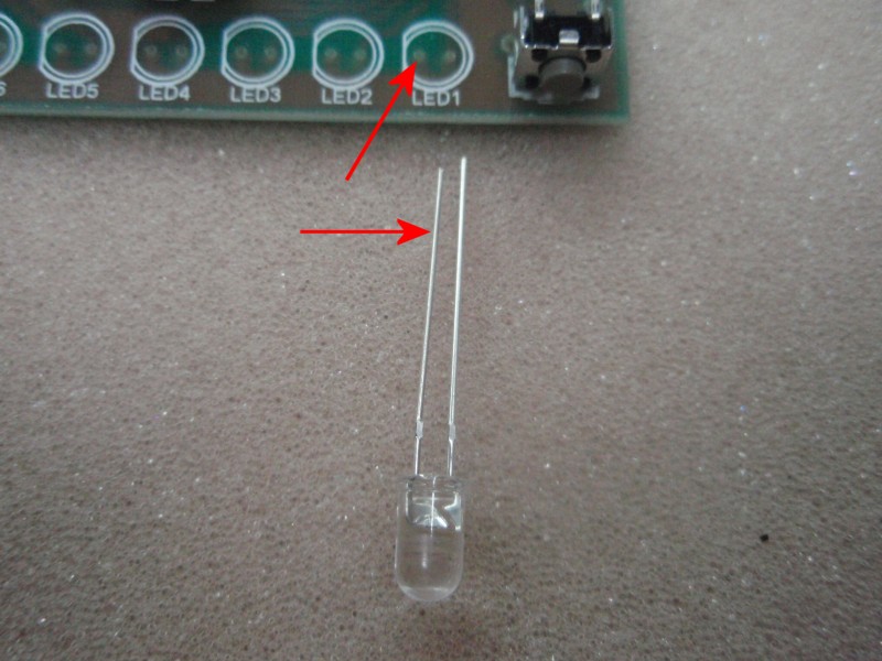
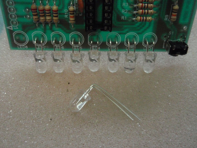
Fig 7.
Next fit the eight LEDs. You will see that one
lead is shorter than the other. The short lead
needs to be fitted into the hole nearest the flat side
of the LED outline on the PCB overlay.
Fig 8./9. You
will need to bend the leads of the LED through 90o
as shown in fig 8. It is advisable to solder
only one lead of each LED. Once they are all in
place you can move the LED body to get them all aligned
before soldering the other leads. If you solder
both leads you risk ripping the copper track off the PCB
if you try to align the LED bodies.
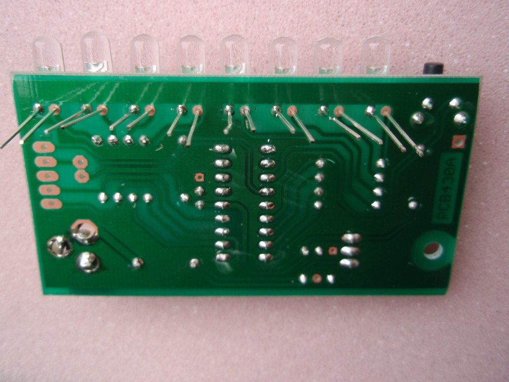
With the PCB assembled but
without the PIC installed in the socket, apply power to the
board and check that the regulator isn't warm. If you have a
voltmeter handy, make sure it measures a nominal 5 volts between
pins 5 and 14 of the IC socket. (somewhere between 4 .8V to
5.2V is normal)
|
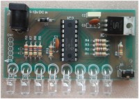
Fig.10 |

Fig.11 |
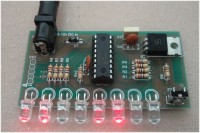
Fig.12 |
| |
|
|
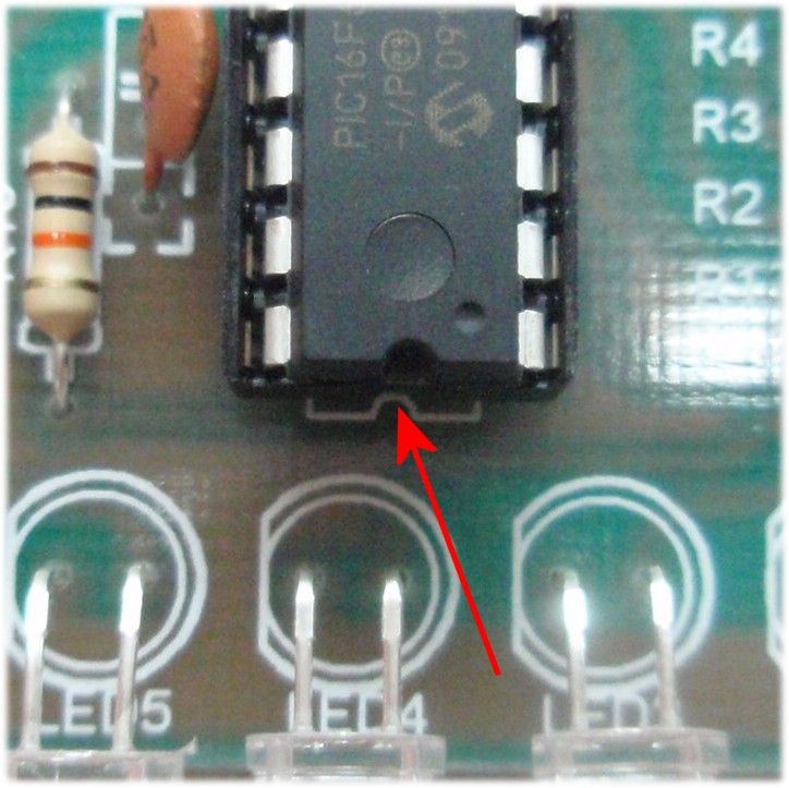
Fig. 10./11. With
everything assembled and having tested the 5 volt supply,
disconnect power from the board. Then insert the PIC
microcontroller, IC2 into the socket. Be sure to fit it
the correct way round. In fig 11 you can see a close up of
the notch in one end of the PIC's plastic body. This must
be aligned with the notch in the socket.
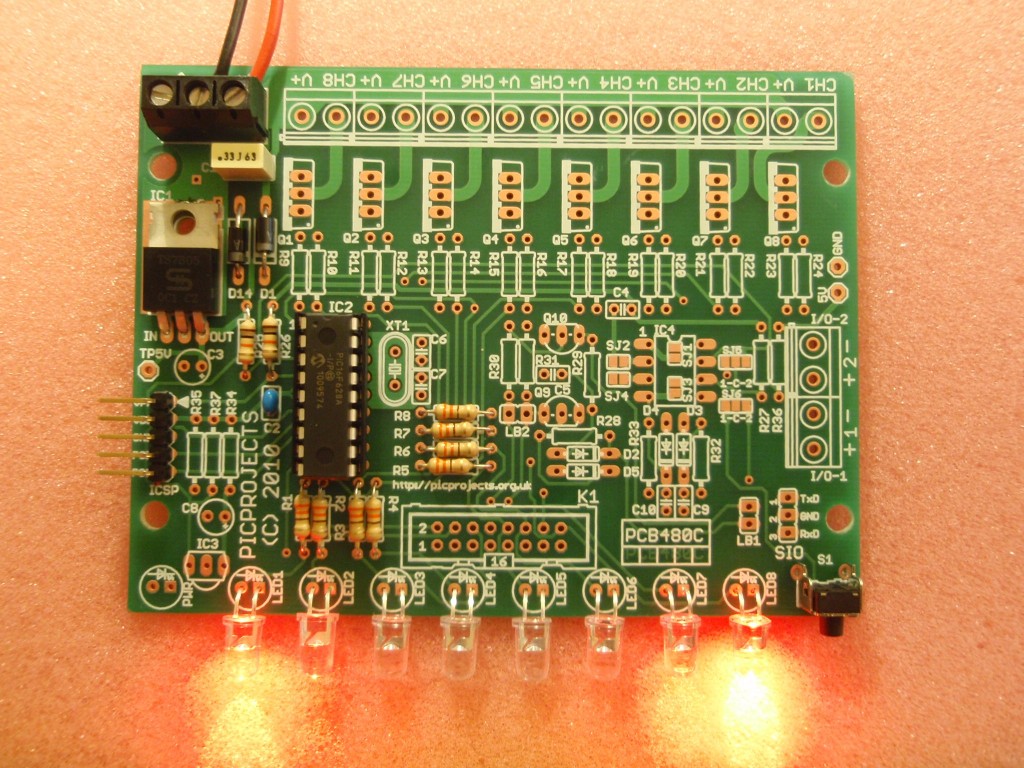
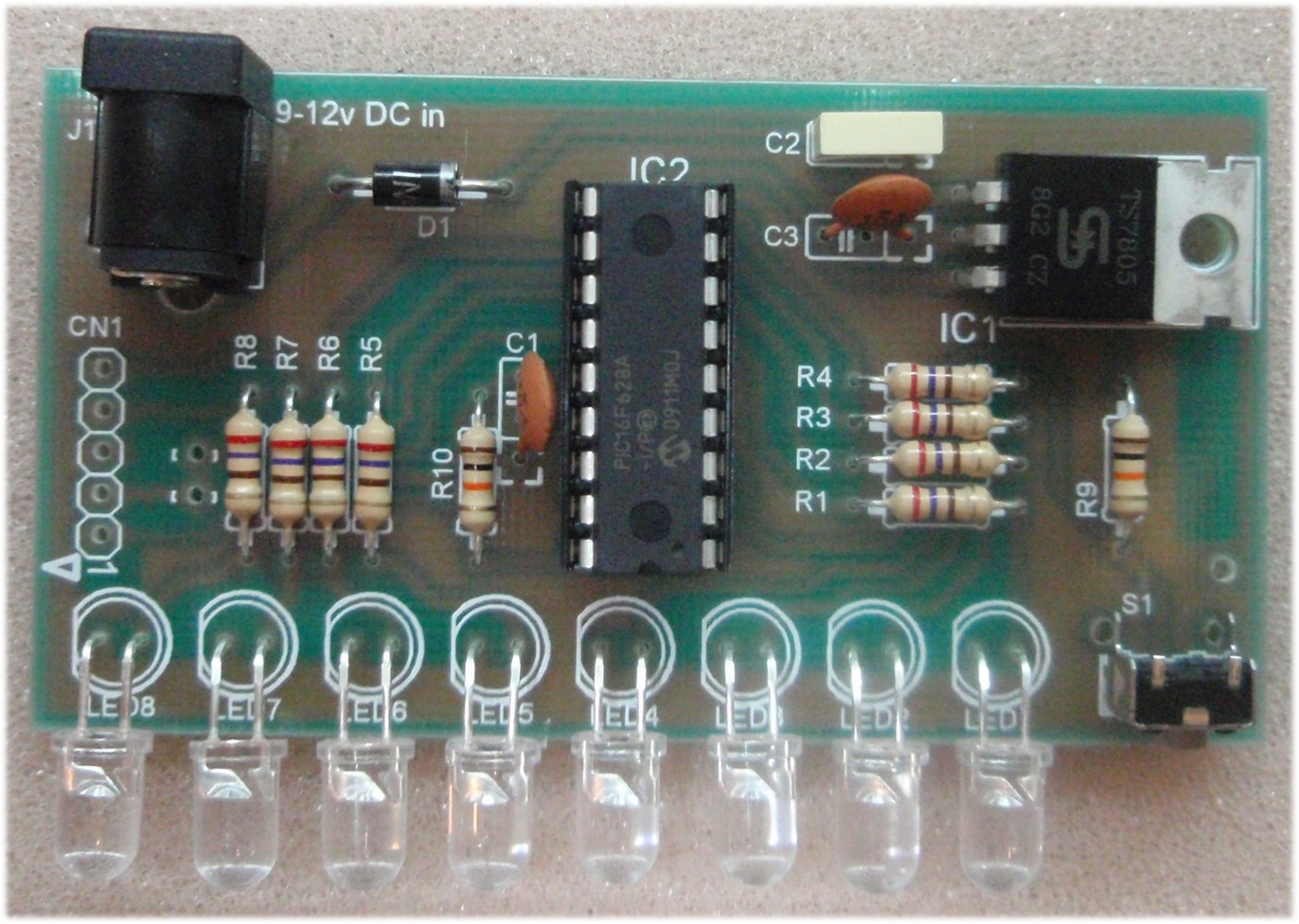
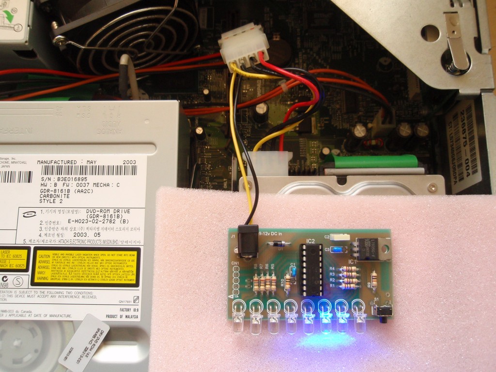
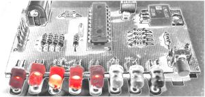
Fig 12. This
photo show the completed LED chaser operating.
Power Supply
The board includes a 5 volt
regulator and reverse polarity protection diode on board.
You will need to use a suitable DC power supply rated between 8
and 12 volts and able to supply at least 150mA.
In the UK you can buy a suitable power supply from Rapid Electronics.
The part number for this is included in
the component listing above should you not already have
something available.
Fitting into a PC case
If you plan on using this
inside a PC as a case mod' you can power it from the PC power
supply.
You have two choices.
- Use the design unaltered
and take the 12 volt supply from the computer fed to the DC
jack input.
- Don't fit the 7805 voltage
regulator and instead use the computers 5 volt power supply.
Connect it where the ground and 5 volt out pins of the
regulator were, leave the regulator input side unused.
For either method if you're
taking the power from a 4 pin drive connector ensure the
unused power connection can't short out on anything inside the
case.
When fitting the LED chaser
PCB, make sure the bottom of the circuit board can't short out
on any metal work inside the case.
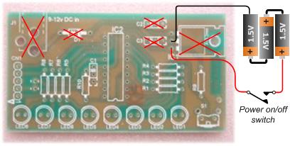
Operation from Battery
If it suits your application,
the circuit can be powered from batteries.
You will need to omit the
following parts: J1, D1, C2, C3 and IC1 (marked with red
'x' in the diagram)
Use 3 x 1.5 volt batteries. e.g. AA / MN1500
Connect to the two holes where the the Gnd and Vout pins of IC1
would have been located as shown.
Rechargeable NiMH or NiCd can be used but since their output
voltage is only 1.2 volts, you need to use four.
(Without D1 there is no reverse
polarity protection so ensure the battery connections are
correct)
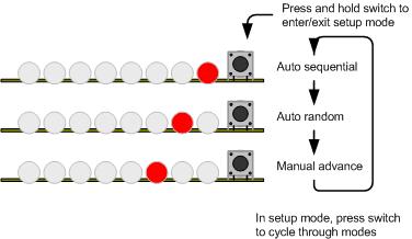
User Operation Guide
The program has three modes of
operation.
- Manual mode will run the
same sequence continually. When the switch is pressed it
will skip to the next sequence in program memory.
- In auto-sequential mode,
the program runs through each sequence in program memory
until it reaches the end of all defined sequences at which
point it restarts from the first one.
- In random mode the program
selects sequences randomly.
When the code is running in any
mode, a short press of the switch will make the controller skip
to the next sequence.
To enter setup mode, press and
hold the switch. Once it enters setup mode one of three
LEDs will light indicating the current run mode. A short
press of the switch cycles through the three modes. When the
desired run mode has been selected, press and hold the switch to
exit setup and return to run mode.
The current mode and selected
sequence are automatically saved to the PICs internal
non-volatile EEPROM memory 10 seconds after the last switch
press. When the LED chaser is next powered up it will load
and start running using the saved mode and sequence. (this
feature is
new from V1.0.4 firmware)
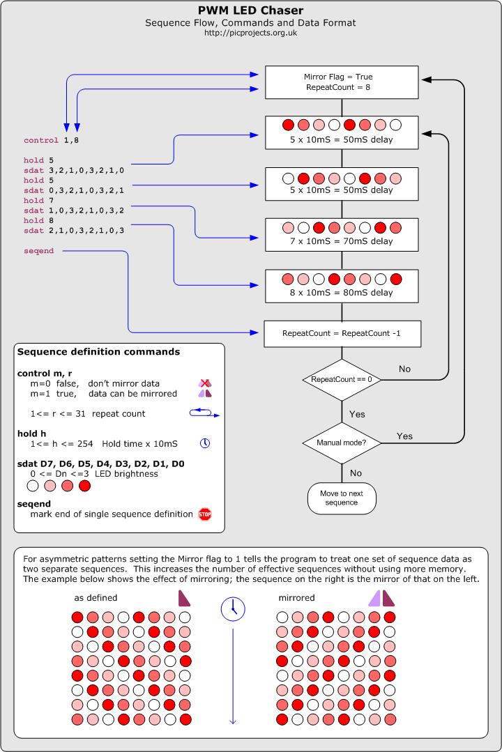
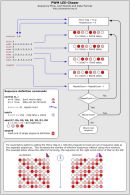
Description of Sequence Data
| The data
used to create the sequences is held in a separate
include file. You can add, remove or edit this
data to create your own chaser sequences.
To make the creation of
the data file easier a set of macros have been defined
which are used to create the sequence data. This
is described in the
Sequence data flowchart
(also available
as a JPEG image right)
If you download the
source code and look at the file named
pwmc_SeqData.inc you can see the data used in the
project. You might want to edit this file as a
starting point to create some sequences of your own.
Notes:
- In manual mode,
when the repeat count reaches zero it will restart
the same sequence, to advance to the next sequence
press the switch.
- In Random mode it
will the select a random sequence number to run. If
the Mirror flag is true for that sequence it will
also randomly choose to mirror the data or not.
- In auto-sequential
mode if the Mirror flag is true it will run the
sequence and then repeat it with the data mirrored.
|
 |
Firmware
The PIC microcontroller
requires programming with the firmware which you can download
below.
The HEX files are ready to
program straight into the respective PIC chip. The latest
code version 1.0.7 supports the PIC 16F628/628A and PIC 16F88
microcontrollers.
It can also be assembled to
work with PIC 16F84 and 16F627/627A but see
note below
The Source code will allow you
to create your own sequences and then reassemble the code to use
them. Quick guide to
reassembling firmware using MPLAB
If you need a PIC Programmer I
strongly recommend the
Microchip PICKit 2,
this is available from suppliers world wide or direct from
Microchip. It's reasonably cheap to buy and reliable.
I have a couple of them and I wouldn't use anything else now.
Not got a programmer? Buy
a pre-programmed PIC from the
On-line store
Supported PICs
The PIC 16F628A is a newer revision
of the 16F628. As far as the circuit and firmware on this page
are concerned the two are functionally identical and you can use
either part.
The PIC 16F84A can also be used
with the firmware on this page. You will however need to make changes to the
hardware design and PCB layout to include an external 4Mhz crystal
and load capacitors or a ceramic
resonator, since the 16F84A doesn't have the internal oscillator of
the 16F628A.
The PIC16F84A and 16F627/627A only
have 1K of program memory. You will need to remove some of the
sequences from
the pwmc_SeqDat.inc file before assembling the code otherwise
it won't fit in the limited program memory on these devices. (MPLAB
will generate errors if the code is too big for the device)
FAQ
Can you or
how can I make it it run
more than 8 LEDs?
This is probably the most
frequent of the frequently asked questions :-)
The project is an 8 LED Chaser
and the firmware was written to work as an 8 LED chaser.
There is no quick and easy
change to make it a 9, 12 or some other number of LED chaser.
If you need a chaser with more LEDs then this project is not
suitable for your needs.
How can I add
more LEDs to each channel?
You can't add more LEDs
directly to the PCB, however, if you want to construct your own
circuit you can add more LEDs to each channel by using an NPN
transistor.
see the PDF document
drivingLEDs.pdf
Will it work
with 3mm LEDs?
Yes, 3mm LEDs will work as will
8mm and 10mm LEDs. 3mm LEDs can be mounted on the PCB, 8mm
and 10mm LEDs would need to be connected by flying leads.
Can I use
less than 8 LEDs?
Yes, since the sequences are
user definable you can create sequences that use less than 8
LEDs.
I only want
it to run one sequence, can it do that?
Since the current mode and
selected sequence are saved to NVRAM, it always powers up in the
last mode and running the last sequence. Therefore if you
select manual mode and the sequence required, it will run only
that sequence until you change it.
Do the LEDs
have to be the same colour?
No they don't. If you
want you can mix different coloured LEDs. You can also mix
3mm/5mm/8mm/10mm LEDs if you want too.
Can I get
the sequences used on the round LED chaser?
The YouTube video clips of the round
LED chaser are running the same sequences as the inline chaser.
They are all included in the HEX file available to download from this
page.
Can you add
a button or potentiometer to change the speed?
The sequences don't have a
speed as such, the data for each step in a sequences includes a
hold time which has to elapse before moving to the next step in
the sequence. This hold time is user defined and can be
different for each step in a sequence. The speed a
sequence runs at is therefore fixed in the data and there is no
option to speed up or slow down a sequence when it is running.
See Description of
Sequence Data
Can it run
from a 12volt car battery?
Yes, should work fine from a
car battery. We suggest you include an in-line fuse of
500mA in series with the power lead to the board.
Can you
modify the code to run on a PIC type xyz?
The code has been written to
run on three of the most popular PICs available. If you
want to modify the source code it could be made to run on other
PIC types, however we won't modify the code.
|