|
3-Channel IR Relay Controller
with user programmable IR commands
for PIC12F629
|
 |
Description
|
This project is a 3 channel
infrared (IR) remote controlled relay driver. It works
with 12-bit SIRC IR signals as used by Sony remote controls.
The controller also features
the ability for the user to 'program' the commands it will
respond to using the IR remote control. Each
of the
three relay channels can also be individually configured for
either toggle or
momentary switch action.
Although this project has been
designed around the control of three relays, the PIC
microcontroller can be incorporated in to any application where
up to three logic level outputs are required to be remotely
controlled.
The controller uses Microchip's
low cost PIC12F629 microcontroller along with a handful of easy
to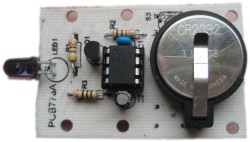 find components making it cheap and easy to construct. Everything you
need to know to build this project, including the firmware code is right here on the project
page. If you don't have access to
a PIC programmer you can buy the PIC chip pre-programmed from
the online-store find components making it cheap and easy to construct. Everything you
need to know to build this project, including the firmware code is right here on the project
page. If you don't have access to
a PIC programmer you can buy the PIC chip pre-programmed from
the online-store
Don't
forget to check out the accompanying
mini IR
remote control which can be used with this
project.
|
|
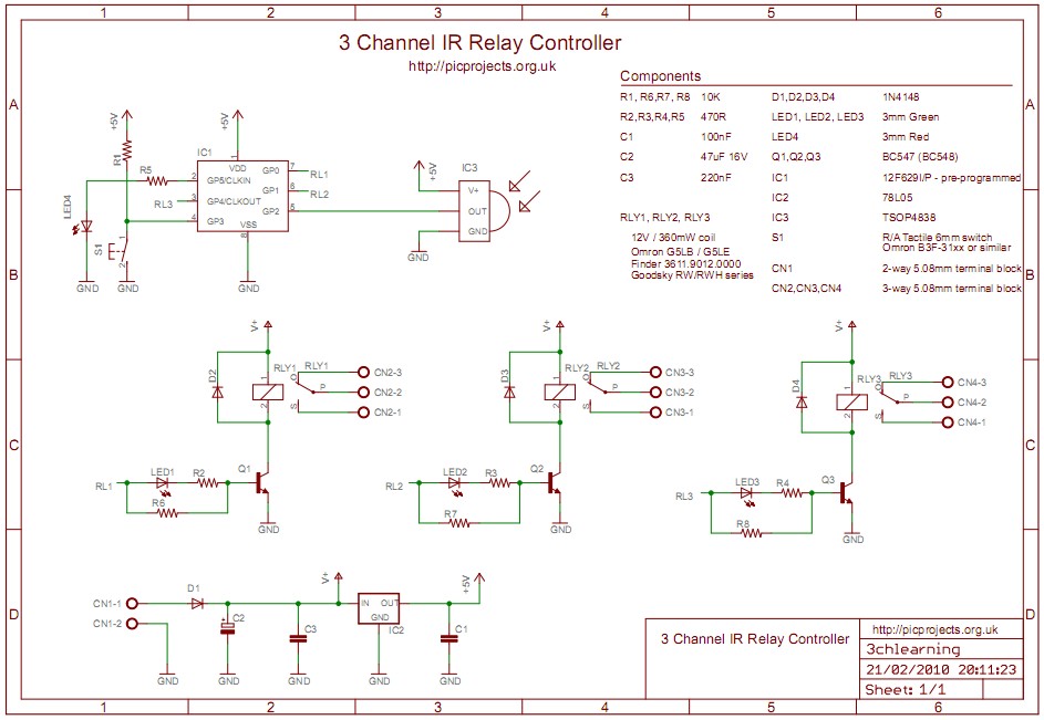
Schematic
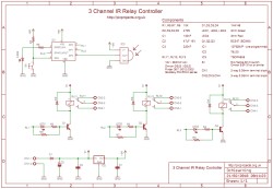
Download
schematic in PDF

Circuit Description
The board is powered from a 12
volt DC supply input. This is fed through diode D5 which provides protection from a reversed
connection of the power supply. Capacitor C2/C3
filter / decouple the 12 volt supply. The 12 volt input is fed to a
78L05 voltage regulator to provide the 5 volt supply required
for the PIC microcontroller IC1 and the IR receiver IC3.
The IR signal is detected and demodulated by
IC3
a TSOP4838 IR receiver IC. This part was chosen because it has a low
supply current requirement - typically around 1.5mA. The
output from the detector is fed to the GP2 input of
microcontroller IC1. When a signal is received by the
TSOP4838 it pulls the GP2 input on the PIC low, when no signal is received it is pulled high by an
internal pull-up resistor. The firmware programmed
into the PIC12F629, IC1 decodes the signal using the 12-bit SIRC
protocol (see download section).
n.b. The circuit and code will
work without modification using either a PIC12F629 or PIC12F675
The relays are switched on by
microcontroller IC1 via driver transistors Q1, Q2 and Q3. These are low power NPN transistors, in
this case BC547 but virtually any small NPN transistor will work
here as they only need to switch around 30mA - BC548 or BC549
would also work well. The relay status LEDs are connected
in series with the base of the relay drive transistor. When one
of the outputs of IC1 goes high, around 5mA passes through the
respective LED and 470ohm resistor to the base of the
transistor, causing both the LED and transistor to turn on and activate the relay.
When the output of IC1 goes low, the 10K resistor holds the base
of the transistor at 0V ensuring it turns off and the relay
deactivates. The diodes across the relay coils protect the
transistor from the back EMF generated by the relay coil when it
is de-energised.
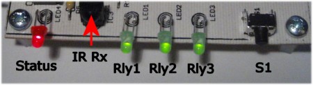
LED 4 is a status LED, in
normal operation it indicates when an IR command is being
received by flashing at 20Hz. It is also used to indicate
that the controller is in setup mode. Switch S1 is used to enter
and exit setup mode, details of this are covered in the
User
Programming
section.
For more information on the
SIRC infrared protocol and codes see:
PCB Layout
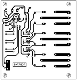
Download PCB
artwork in PDF
Download PCB
overlay in PDF
PCB dimensions are 80mm x 75mm
approx.
Suggested hole drill sizes:
- terminal blocks and S1
metal frame drill at
1.1mm
- relays drill at 1.5mm
- U1, U3 drill at 0.85mm
- PCB mounting holes drill
at 3mm
- everything else drill at
0.75mm
Component List
You can buy all the parts
needed to build this project from most component suppliers world
wide. In the UK you can get everything from Rapid Online and
I've included a parts list with their part numbers below.

All
Rapid parts/descriptions correct at 21 February 2010. You should
check part# and descriptions are correct when ordering in case
I've made a mistake transferring them onto this page.
|
Component |
Description |
Part # |
| R1,6,7,8
* |
PACK 100 10K 0.25W CF
RESISTOR (RC)
|
62-0394
|
| R2,3,4,5
* |
PACK 100 470R 0.25W CF
RESISTOR (RC) |
62-0362 |
| C1 |
100N 2.5MM Y5V
DIELEC.CERAMIC (RC) |
08-0275
|
| C2 |
47U 25V 105 DEG.RADIAL
ELECT. (RC) |
11-1165
|
| C3 |
220NF 63V 5MM
POLYESTER BOX CAPACITOR RC |
10-3264
|
| |
|
|
| D1,2,3,4 |
1N4148 75V 200 MA
SIGNAL DIODE. (RC) |
47-3309
|
| Q1,2,3 |
BC547B TRANSISTOR NPN
TO-92 50V (RC) |
81-0468
|
| LED1,2,3 |
L-7104GT LED 3MM
TRANSPARENT GREEN (RC) |
56-0555 |
| LED4 |
3MM TRANSPARENT RED
LED (RC) |
56-0550
|
| IC1** |
PIC12F629-I/P (RC)
|
73-3262
|
| IC2 |
DA78L05 V REG +5V
100MA TO-92 TRU (RC) |
47-3612
|
| IC3 |
TSOP4838 IR RECEIVER
MODULE 38KHZ (RC) |
55-0905
|
| RLY1/2/3*** |
36.11 12V
MINIATURE SPDT 10A RELAY RC |
60-4192 |
| socket for U1 |
8 PIN 0.3IN TURNED PIN
SOCKET(RC) |
22-1720
|
| CN2,3,4 |
3 WAY 16A INTERLOCKING
TERMINAL BLOCK RC |
21-0442
|
| CN1 |
2 WAY 16A INTERLOCKING
TERMINAL BLOCK RC |
21-0440
|
| S1 |
5.85MM RIGHT ANGLE
TACT SWITCH (RC) |
78-1154
|
Parts List Notes
*
All the resistors are
supplied in packs of 100 so only order 1 pack of each.
**
PIC12F629 will need programming with the firmware (see
Firmware download section)
Not got a
programmer? Buy a pre-programmed PIC for this project from
the online store
***
PCB uses a standard relay footprint, alternative manufacturers
products can be used.
Suggested alternatives are listed at the end of the Construction
section
Construction
Photos & Notes
Construction is very
straightforward however, before you start please read
through this section so you know what to do, the photo's are
clickable to get a 1024x768 detailed version.
Fig.1 |
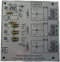
Fig .2 |
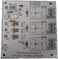
Fig. 3 |
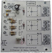
Fig.4 |
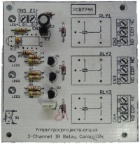
Fig.5 |
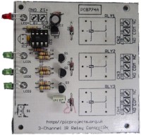
Fig.6 |
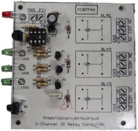
Fig.7 |
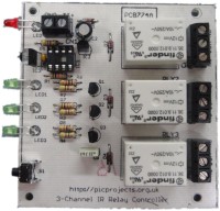
Fig.8 |
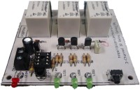
Fig.9 |
Construction notes
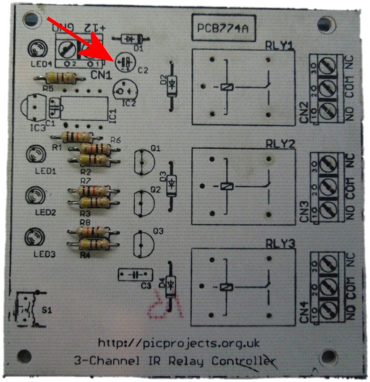
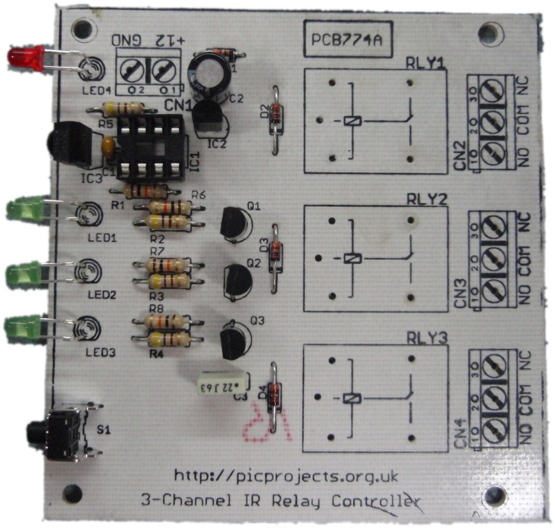
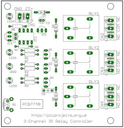
Fig 1. The PCB without
any components installed showing the component overlay markings.
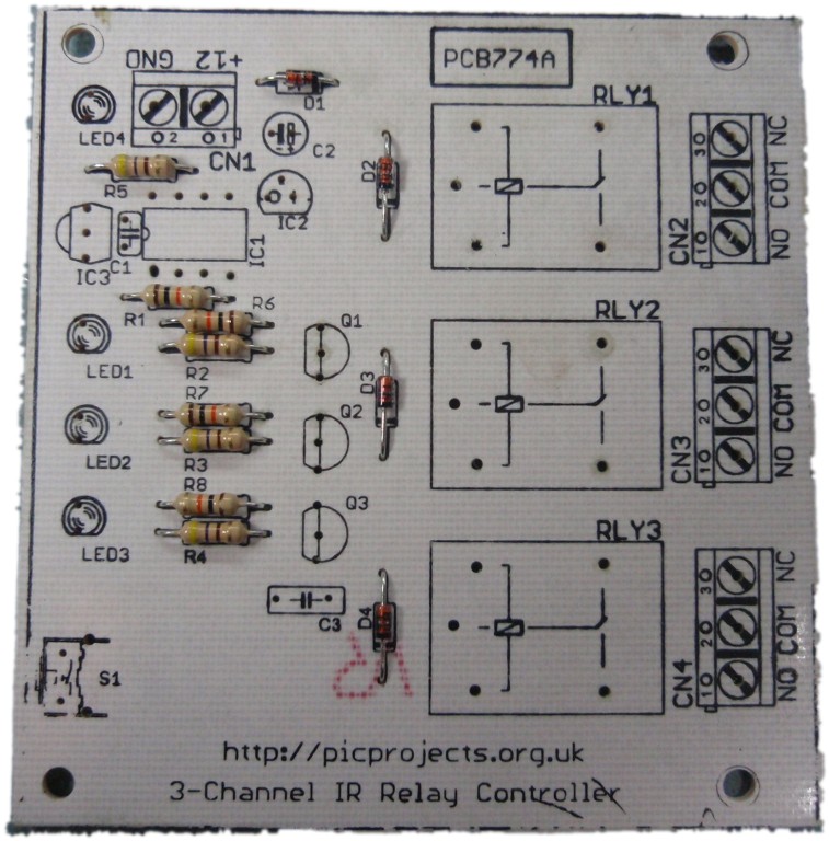
Fig 2. Install the
resistors. Doesn't matter which way round these go but it does
matter what values go where. Check the coloured bands
R1,6,7,8 are 10K

R2,3,4,5
are 470R

Fig 3. Install
the four 1N4148 diodes. Make sure the black band marking on the diode
matches the overlay.
Fig 4. Now fit
capacitors C1, C2 and C3. C3 is the 47uF capacitor and as it's a polarised part
it needs to be fitted the correct way round. One of the leads
will be shorter than the other. The short lead is the negative
terminal and should be fitted so it is on the side arrowed in the
photo (click on photo).
Fig 5. Next install the
three BC547 transistors Q1,2,3 and the 78L05 voltage regulator IC2. These need
fitting the correct way round, align the body of the part as shown
in the photos. Don't get IC2 mixed up with the
transistors, since physically they look the same. If you look
closely at the flat face of these parts, the part numbers are
laser etched on them.
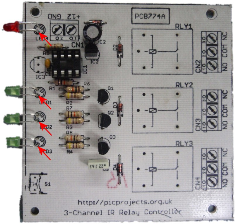
Fig 6. Fit the socket
for IC1 and the four LEDs. The LEDs must be fitted the correct
way round. On each LED one lead is shorter than the other,
this denotes the Cathode terminal. The Cathodes all need to be
fitted in the hole towards the bottom edge of the PCB as seen in the
photo. This is shown arrowed in the large image (Click on the
photo) You will also need to bend the leads through 90o
so the LEDs face in the same direction as the front of IC3 and the
switch.
 At this point, before IC1 and IC3
are installed it is advised to apply 12 volts to the power terminal.
Then using a voltmeter, measure the voltage between pins 1 (Vdd) and
8 (Vss) of
the IC1 socket. It should measure 5.0 volts, if it doesn't find
out why and correct it before moving on.
At this point, before IC1 and IC3
are installed it is advised to apply 12 volts to the power terminal.
Then using a voltmeter, measure the voltage between pins 1 (Vdd) and
8 (Vss) of
the IC1 socket. It should measure 5.0 volts, if it doesn't find
out why and correct it before moving on.
Once you've tested the power,
disconnect the 12 volts supply - never work on a board with power
connected.
Fig 7. Now fit the the
IR receiver IC3 and switch S1
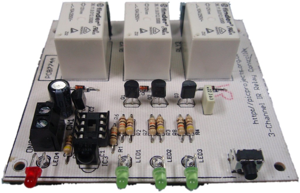
Fig 8. Finishing up,
fit the four screw terminal connectors and three relays.
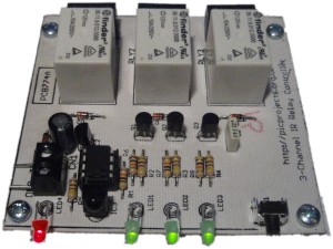
Fig
9. View of the assembled
PCB from the front
All done. Give the
board a once over checking for bad solder joints, bridges and
anything else that doesn't look right. If you're happy with the
construction, apply 12
volt power supply and recheck the 5.0 volts between pins 1 and 8 of
IC1 socket. If it's correct then it's time to install the PIC
microcontroller IC1 into the socket.
If you haven't already done so,
program the PIC with the firmware at the
bottom of this web page.
Operating
The code in the download section is set for a Sony TV remote and
the following command buttons:
- #1 - Relay 1 Toggle
- #2 - Relay 2 Toggle
- #9 - Relay 3 Toggle
You can use a one-for-all type
remote control set for a Sony TV, or take a look at the mini IR
remote control project here
designed to work with this relay board.
The relay controller can be
user programmed to respond to any 12-bit SIRC control code, and
in addition each output can be set to toggle or momentary
action.
The default codes supplied can
easily be changed by entering setup mode and reprogramming the
command codes. Details of how to do this are in the
User
Programming section.
Power Supply
The board needs a 12 volt DC
regulated supply. Current draw is about 110mA with all
three relays on and around 10mA with relays off..
Relays
The relay
footprint is a standard size so the board can accommodate many
different makes / models. Just ensure that they are rated
for 12 volt operation and 360-400mW coil power.
Some that should
work are listed below:
Omron G5LB,
G5LE
Finder 3611.9012.0000
Goodsky RW/RWH series
Matsushita JS series
Firmware
The HEX file is ready to
program straight into the PIC using a suitable PIC programmer,
for example a PICkit2.
Not got a
programmer? Buy a pre-programmed PIC for this project from
the online store
|
Description |
Filename |
Download link |
Sorce assembler file for 12F629 and 12F675
|
3chlrnrem2975.ASM 15/09/2011
Conditions of use |
 download
|
HEX file
for 12F629 and 12F675 ready to program
|
3chlrnrem2975.HEX 15/09/2011
Conditions of use |
download
checksum 0xE436 |
If after programming with the HEX file, the status LED (LED4) is
lit continually, then the calibration word is missing from the
12F629. - see here for more
information on the calibration word
User
Programming IR commands and output action
The relay controller can be user
programmed to respond to any 12-bit SIRC commands. In addition
to this the action of the outputs can be programmed to either toggle
on/off or momentary on where the output is only active while the IR
signal is being received from the remote control.
- With the controller board
powered on, enter setup mode by pressing S1 for about
1.2 seconds
- The Status LED will start to
flash at 1Hz and the Rly 1 LED will light.
- Press the button on the remote
control you wish to use to operate Relay 1.
When a valid command has been received it will turn off Rly 1
LED and Rly 2 LED will light.
- Press the button on the remote
control you wish to use to operate Relay 2
When a valid command has been received it will turn off Rly 2
LED and Rly 3 LED will light.
- Press the button on the remote
control you wish to use to operate Relay 3
When a valid command has been received for Rly 3, the
Status
LED will begin to flash at 3Hz and all three Rly LEDs will
turn off.
- Set output operating action.
By pressing the buttons
programmed in steps 3 to 5 above, the Rly LEDs can be turned on and off.
When the LED is off, the corresponding relay will operate in
toggle action mode. When the LED is on, the relay will
operate with momentary action.
- Once the desired operating mode has
been set for each relay, press switch S1 again.
- The Status LED will turn off
and the settings are saved to non-volatile memory.
The controller will now respond
to the newly programmed commands
Notes:
- Once in setup mode, you must
program each relay before you can exit, if you make a mistake
during programming, complete programming and press switch
S1 to exit, then simply re-enter setup mode again and reprogram
the commands.
Alternatively you can just cycle power to the controller.
- If you program the same remote
control button to more than one relay, only the lowest number relay
output will respond to that remote control button.
Therefore each relay should be programmed to respond to a unique
remote control button.
Contact us:
 |