|
|
Serial
Controlled
RGB LED PWM
Driver
12F6xx based PWM
controller for RGB LEDs
|
 |
Description
If you want to build your own multiple
RGB LED display that you can control from either a PC or a dedicated
controller then this project will let you do just that.
The project on this page came about
when while I was developing a more complex intelligent
driver. During that work I put together a simple Red/Green/Blue Pulse
Width Modulation LED driver that has a serial
interface. The RGB values to control the LED brightness are sent
to the PWM driver over this serial interface.
With both the original and revised
versions of the RGB PWM driver there was one big shortcoming when you
want to have several drivers working together. Even when they're
running the same sequence, the small differences in the frequency of the
internal RC oscillator cause some to run the sequence slightly faster,
others slower. The result, well sometimes it's quite effective,
but mostly it just looks awful.
With the controller / driver presented
here it is possible to connect multiple drivers to the same serial
cable, all attached units then appear to operate synchronously since
they're all receiving the same control data. The PCB for the RGB PWM Driver has been designed so
that it can be used with both the serial control firmware on this page,
or the standalone firmware here
The serial data can be sent from the
serial COM port of a PC or using a small dedicated controller that I've
put together. The Controller code is based on the standalone RGB driver
code described elsewhere on this
website. The controller uses the same format for the sequence data as the
standalone RGB driver so any SequenceData.inc files you have for the standalone
driver can be used with the Serial RGB Controller.
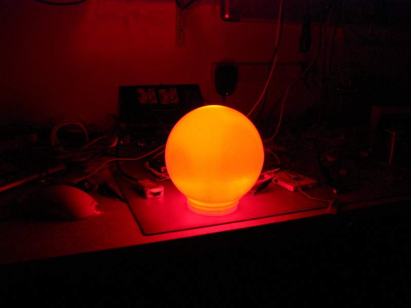
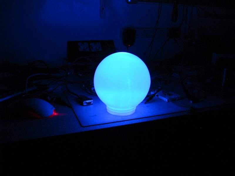
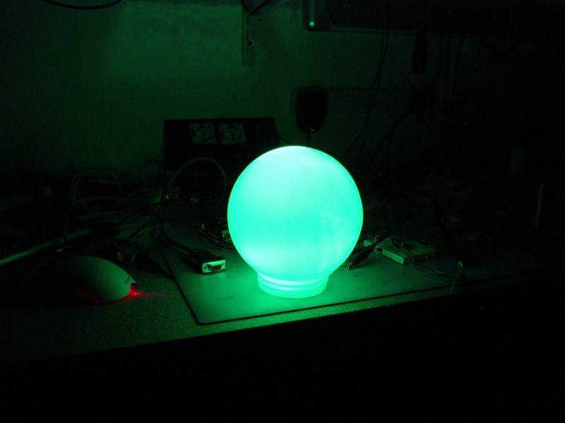
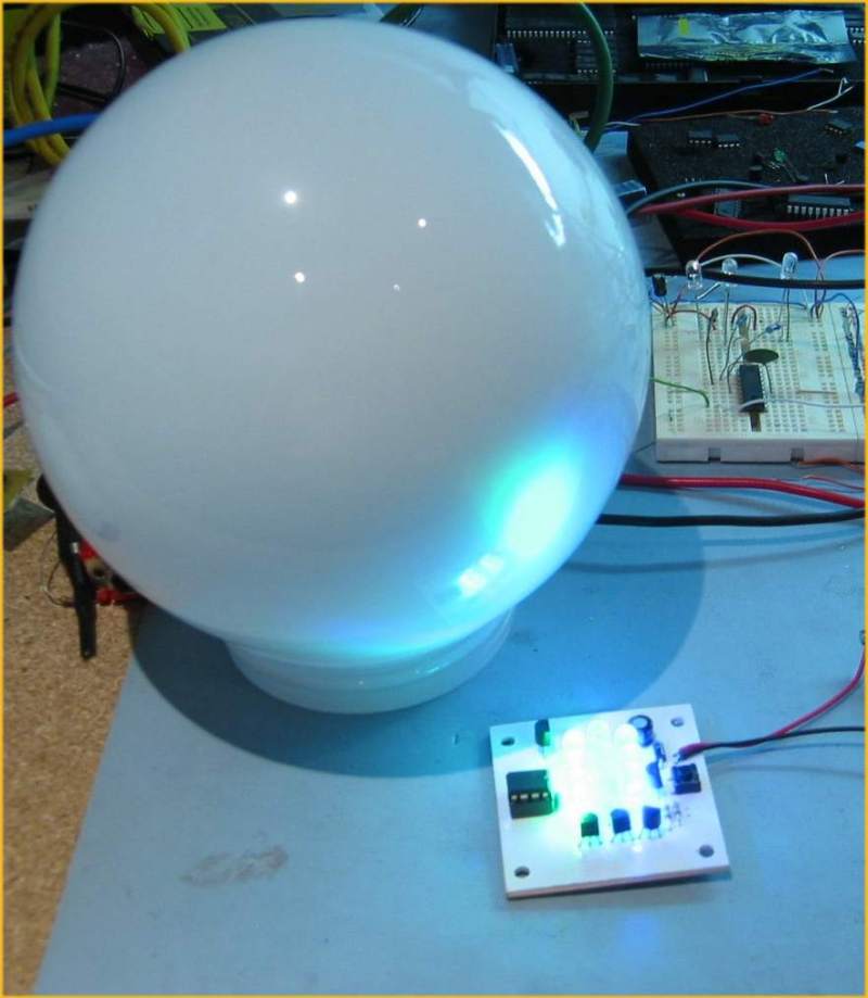
The pictures below show an RGB Driver
placed inside a 6" opal glass light fitting. I bought this from a
DIY store for £4.99 (see
here). When the LED driver is fitted in the base it
illuminates the whole globe. Because most 5mm LEDs have quite a
narrow viewing angle you tend to got 'hot spots' in the top but overall
it's very effective and makes for great mood lighting. (In
case it isn't obvious you do not connect the light fitting to the mains
electricity supply when used with the RGB Driver!!!)
Also check this mood light by Pete Rus
which is based on the Standalone PIC controller
http://www.instructables.com/id/E5A6O59KDPEUSZO1BK/?ALLSTEPS
How it works
Back to the RGB LED Driver.
Depending on which firmware you program into the PIC this PCB and
hardware can
operate as either a serial controlled driver or a stand-alone driver (see
here).
Serial Data Format
Serial Data is sent to the RGB PWM Driver
using a standard 2400bps asynchronous serial data stream (like you get
from the COM port of a PC). The serial frame
format is 1 start bit, 8 data bits, 1 stop bit. RS232
devices, including the PC COM port, always generate a start bit so when
you look at the serial port parameters in Windows you won't see it as an
option. Use 8N1 for the COM port settings.
The RGB values for the PWM
driver are sent in a five frame packet.

- The first frame must always
contain the value 0x81 (129 decimal)
- The next three frames contain the
8-bit Red, Green and Blue data for the PWM driver.
- The last frame is the checksum.
It should contain the 2's compliment of the sum of the previous four
frames, modulo 256.
The code snippet below shows the checksum computation in PIC
assembler.
movlw
0x81
addfw
RedPWM, W
addfw
GreenPWM, W
addfw
BluePWM, W
sublw
0x00
movwf
chksum
The Serial RGB Controller will take care
of all this for you. However, if you write an application to generate
the data from a PC the application itself will need to take care of
this.
Controlling from a PC
During development of the Driver I put
together a couple of short Perl scripts for testing purposes. The first
one takes user entered RGB
values and sends them through the PC serial port to the driver.
The second one sends a continuous stream of RGB data to the driver that
generates a 'wave' effect. (Both scripts are hard coded to use
COM1)
At this point I need to make it clear I
am not supporting the Perl scripts. The ability to send data to
the Driver from a PC is a bonus. If you don't know Perl or have no
previous programming experience you will probably be unable to make use
of them.
PLEASE DO NOT e-mail me asking for help with these scripts
I don't like having to say that, but PIC programming I do for fun;
Perl I do not.
The scripts are written for ActivePerl
and require the module Win32::SerialPort.
Some Perl resources - if you want to learn Perl.
If you
write some code for the PC to control the driver boards and you're
prepared to share it, let me know and I'll be happy to link to it from here.
Addressable version of the Serial
controlled RGB PWM driver (added January 2011)
IMPORTANT: Please be absolutely
clear about this: it's available, it's free, it does work and has been
tested but I will not support it, modify it, or help you implement any
application with it. Please don't email me asking for any support -
really.
The project on this webpage is a based
on code I wrote for an addressable RGB controller, it's just a cut down
version. At the time I wrote it I didn't have any supporting
software to send data to the addressable modules, for that reason I
didn't make the addressable code available. I still don't have any
code other than that I used for my own application. I actually
went on to develop the the Serial Addressable RGB PWM
LED/Servo Driver which was much better, if a bit more complex.
However over the last four years I've
been contacted by email on many occasions asking for an addressable
version of this project and I've let people have the code I'm now making
available here on request.
The packet format is described in
detail in the PDF file download:
Packet format

The source code for the addressable
version of the Serial controlled RGB PWM driver can be download
from here
Operation
There are two parts to this
project.
Sends RGB data to the
drivers over a serial interface.
|
|
- Serial RGB LED PWM Driver
Drives RGB LEDs using Pulse
Width Modulation (PWM) at an intensity controlled by the
most recent serial data packet received by the driver.
The
data can be provided by the Serial RGB Controller or from
the COM port (RS232 interface) of a PC.
|
 |
Serial RGB Controller
- When the Serial RGB Controller is first powered on after
programming, it should start running the first RGB sequence found. If
you're using the original sequences supplied with the code it will
run a sequence of red-fade out, green-fade out, blue-fade out
repeatedly.
- Press the SW1 sequence select switch to
step through all available sequences. When the last sequence has been
reached it will go back to the first available sequence. Each time
the SW1 switch is pressed the RGB LED PWM values are set back to 0 (LEDs
off)
- About 10 seconds after the SW1 sequence
switch is last pressed the currently selected sequence number is saved to
non-volatile EEPROM memory. When the Serial Controller is next
powered on, the saved sequence number is read back and will automatically start
running.
Serial RGB LED PWM Driver
- Operation of the Driver is very
straightforward. You send it correctly formatted and
checksum'd packets through its serial interface. It will then
drive the RGB LEDs with those values until it receives another
packet.
- If you're driving it from a PC,
avoid sending a continuous stream of packets back-to-back when the
RGB values have not changed; it serves no useful purpose and causes
the LED's to vary slightly in brightness due to the demands on the
software in processing the serial data stream.
- After power-up the LED's are
turned off and will remain off until it receives valid RGB data over
the serial interface
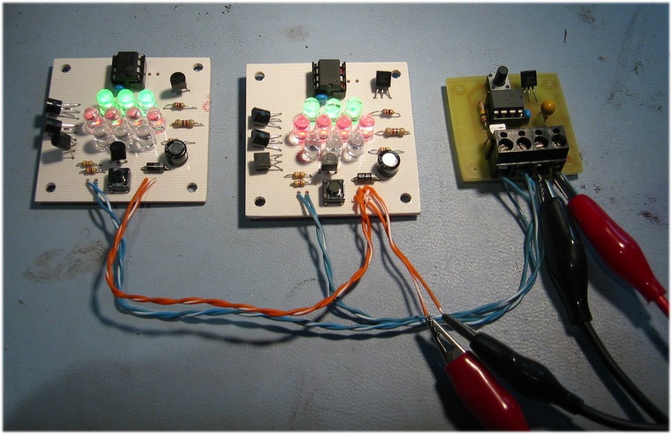
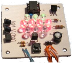
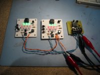
Code, Construction & PCBs
|
Serial RGB
Controller |
Serial RGB LED
PWM Driver |
|
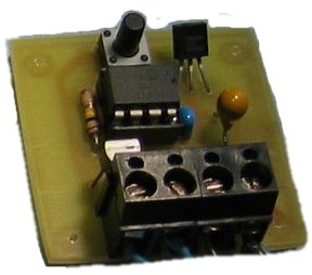
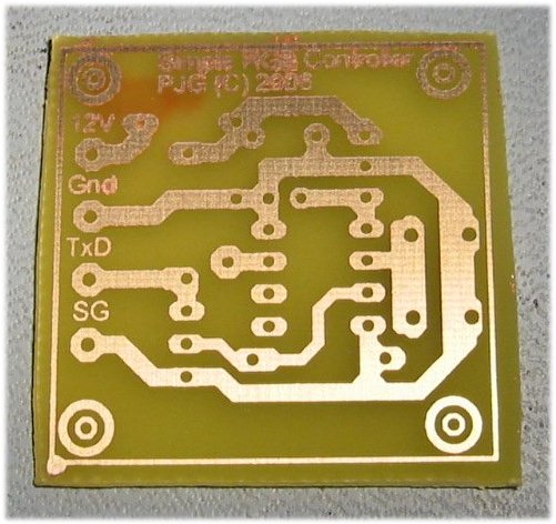
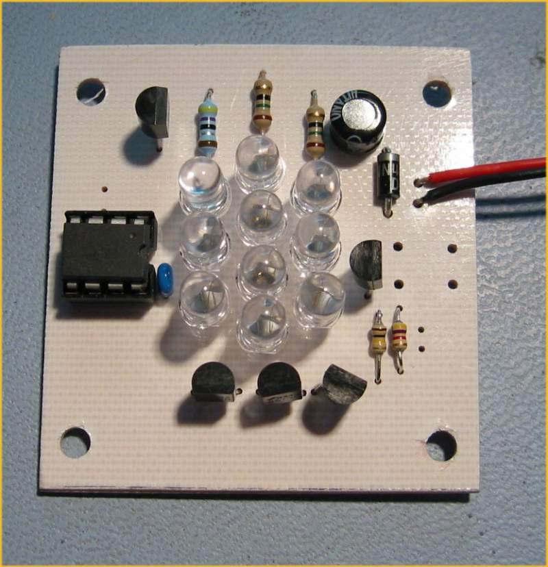
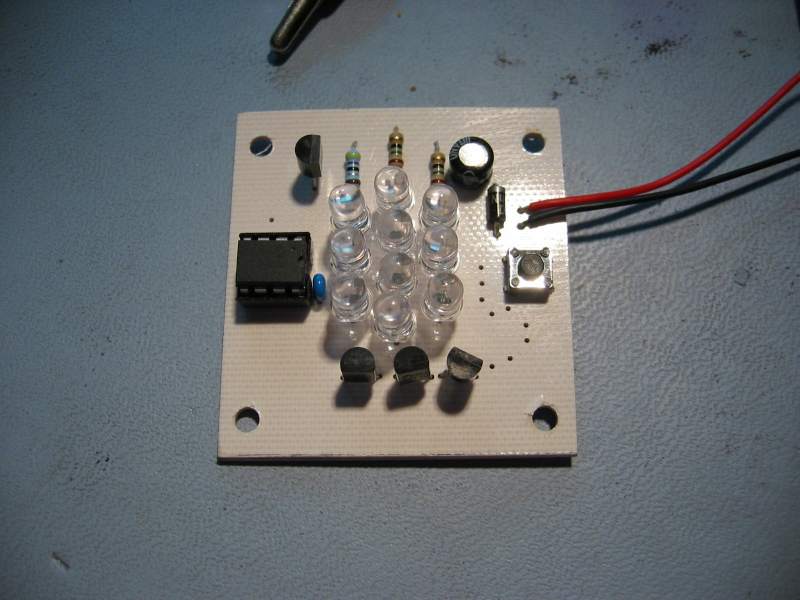
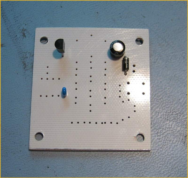
Note: These photo's show
the original PCB layout under construction. I've since
done a second revision to the PCB which is provided in the
files above.
|
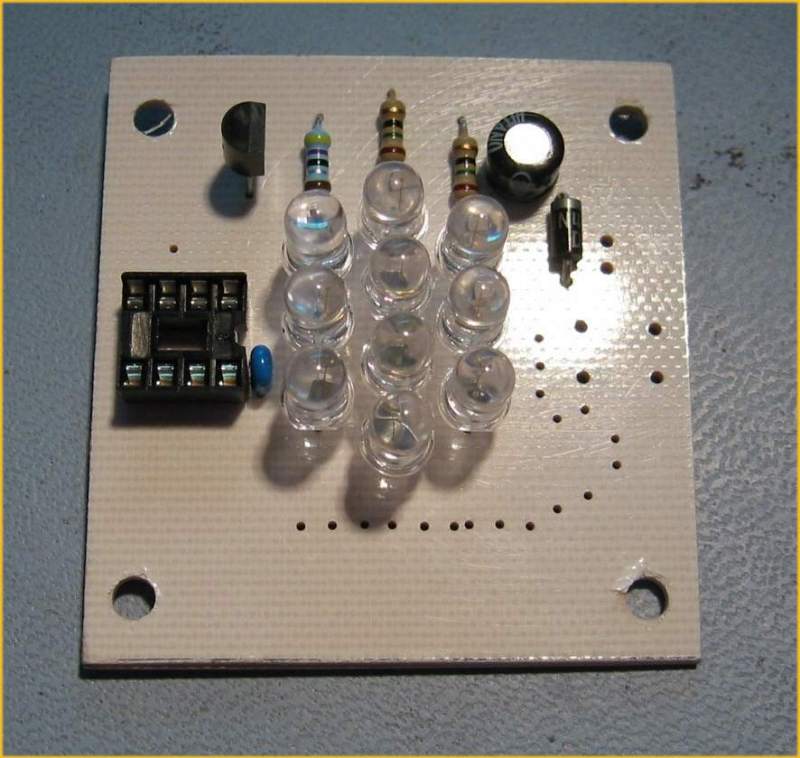
The PCB can be used
with both the Stand-alone firmware and the Serial Controlled
Driver firmware.
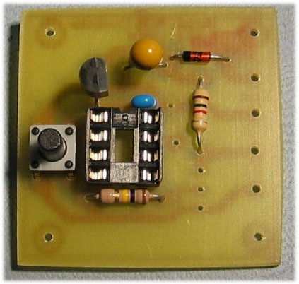
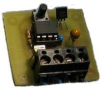
- If you build the
stand-alone version you can omit Q1, R1 & R2
as shown in the picture above right.
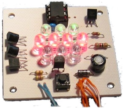
- The Red Green & Blue
LED's are not specified because I expect you will source
these yourself depending on what you want / have / can
afford etc. Therefore you will also need to
calculate the correct series current limiting resistor
required to use with the specific LEDs used.
LED Resistor calculator
- Jumper J1 is not used
on the Serial RGB LED PWM Driver - leave it open.
- Capacitor C3 is
specified as optional. I've never used it and I've never
had any issues. If you check the datasheet for the
78L05 it is recommended if the power supply is more then
75mm (3") from the regulator so I've made provision for
it on the PCB.
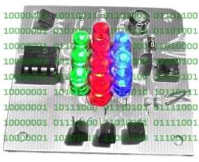
-
Construction tip:
When you solder the LED's to the PCB, only solder
one lead of each LED. Once all the LED's are
fitted, you can move the LEDs around to get them all
neatly aligned. Once you have them aligned, solder
the remaining lead on each LED. If you try moving
them once both leads are soldered you risk ripping the
copper off the PCB.
|
|
|
|
ESD and MOSFETs
Please read this |
 |
|
If you've constructed electronic circuits before and got
away without using good ESD (anti-static)practice, then be warned,
you won't now. Both the controller and driver use
MOSFETs. When you're constructing the
circuit you MUST use ESD precautions
during unpacking, handling, assembly and soldering
otherwise I pretty much guarantee you will destroy one
or more of the MOSFETS. If you're
not using an ESD Soldering Iron make sure you ground the
tip before soldering each MOSFET.
The
maximum gate voltage on the 2N7000 and MOSFETs in general
is typically +/- 20volts, exceed this in use, or through
ESD and it will fail. A short document on ESD and
MOSFETs can be found
here
I'd also
recommend that you buy a few extra 2N7000's, they're not
expensive and if you destroy one and you've got a spare
it won't ruin your day.
|
Firmware and PICs
The firmware for
both the controller and driver will run on the following PICs.
You will need to assemble the code to produce the correct HEX
file for the processor you are using.
The
Serial RGB Controller code is made up of a single .ASM file
named rgbsync_ctrl.asm and several .INC files. All
these files should be placed in a single directory and the rgbsync_ctrl.asm
file loaded into MPLAB and then
assembled to generate the programmer ready .HEX file. The
SequenceData.inc file contains the RGB, Fade and Hold data for
the sequences. You will probably want to edit this file,
put your own sequence data in it, then reassemble rgbsync_ctrl.asm
to include your own sequence data.
Because the serial
bit rate is generated using the PICs internal RC oscillator it
is imperative that for PIC12F629 and 675 chips, the OSCCAL value
located at the top of program memory is correct and present.
If you accidentally erase the OSCCAL value use this
circuit and code to recover it.
Troubleshooting
On the
Serial RGB Controller , TP1 outputs the bit rate clock which should
be a nominal 2.4Khz. If you have a 'scope or frequency meter to hand you
can verify this.
On the Serial RGB
Controller the signal on GPIO4 (pin 3) of the PIC should
idle at 5V and swing between 0v and 5v when transmitting data.
If the signal on
GPIO4 (pin 3) is correct then before connecting the Controller
TxD output to the Driver RxD input, check the signal at the
drain of the MOSFET Q1 ( TxD connector)
on the Controller to make sure the signal there is going between
0v and 11.4V.
If the TxD output
is okay, connect the Controller to the Driver and then check the signal on the RxD input of
the Driver to make sure the signal is present.
On the Serial RGB
Driver, check that there is serial data being received on GPIO5
(pin 2) of the PIC (using an Oscilloscope). This signal
should idle at logic 1 (5volts) and swing between 0v and 5v when
data is being received.
If this is not the
case for either the Controller or the Driver, and particularly
if the signal is present but not swinging between 0v and 5v,
you've probably got a failed MOSFET.
All the 'faults'
I've had during development have been down to failed MOSFETs,
Connecting Up
The following diagrams illustrate,
schematically
how to connect the controller and drivers together.
- Serial RGB Controller and
drivers using a common PSU (PDF)
- Serial RGB Controller and
drivers using individual PSUs (PDF)
- Connecting drivers to a PC
serial COM interface (PDF)
The serial interface on the
controller and driver boards is deliberately simple by design. It is adequate for connecting multiple
drivers over a short distance. You need to decide whether the
basic serial interface circuit is adequate for you particular
application, and if necessary modify the serial interface circuit to
meet your specific requirements. If you're going to connect a number
of drivers over an extended distance to the serial interface of a PC
or the Serial RGB Controller I'd suggest looking at a solution
based on the RS-485
standard. Driver IC's such as the
ST485CN are cheap enough and would be a a good basis to start
from.
Power Supplies
The controller and drivers need a
regulated 12Volt DC Power Supply. Do not use unregulated
DC supplies - these only deliver the rated output voltage under full
load. You could see as much as 17V at the output of an
unregulated 12V supply under partial load. This will damage the LEDs.
A PSU like the one under part
number 85-2902 from Rapid Online - Rapid Electronics Ltd. is ideal and should run the controller and up to ten
RGB LED PWM drivers, depending the specific LEDs used of course.
Format of the Sequence Data
The data
used by the Serial RGB Controller for the RGB sequences is held in the file 'sequenceData.inc'
You can edit this file to add, remove or change the data provided.
You must ensure that it follows the format described. In
particular pay attention to the 'end of sequence' and 'end of all
data' markers and also ensure that each line of sequence data
contains five comma separated entries. (see screen dump below)
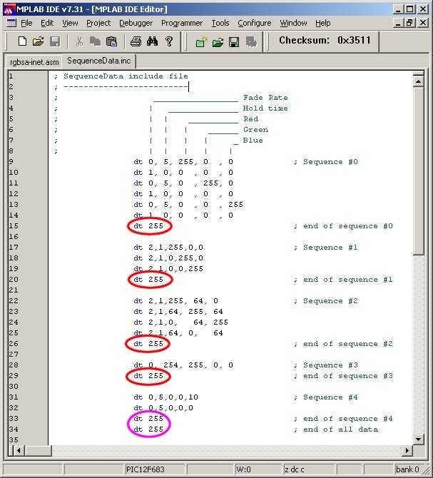
In the
screen dump above note the
'end_of_sequence' markers circled in red and the
'end_of_all_data'
marker circled in purple.
You must
have at least one sequence present up to a maximum of 256 individual
sequences, although you're likely to run out of available memory on
the PIC before you reach this limit.
-
Each line
of data starts with a 'dt' (data table) assembler directive.
-
All data
is specified using decimal values.
-
Each data value must be separated
by a comma
-
The
sequence data on each line has five fields:
-
Fade
Rate: speed the colours fade from the current values to the new
values. Each step occurs at an interval of 5ms x Fade Rate.
-
Hold
Time: after fade completes, delay before moving to next line of
data. Interval is 50mS x Hold Time
-
Red,
Green and Blue PWM values. 0 = 0% (LED off) through to 255
= 100% (LED fully on)
Typically changes in LED brightness are more noticeable between
0 and 128 than from 128 to 255.
-
End
of the current sequence data is indicated by the Fade Rate field
being set to '255'. When the application encounters this
it restarts the sequence from the beginning.
-
At
the end of all available sequence data both the Fade Rate and
Hold Time fields must be set to '255'
After
editing sequenceData.inc the file should be saved and the
rgbsync_ctrl.asm reassembled. The resulting rgbsync_ctrl.hex
file can them be programmed into the PIC.
Note about
Fading
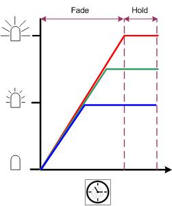
In the
previous versions of the code when the LEDs faded from one colour to
another all three LEDs faded at the same rate, as in fig 2.
Neither method is right or wrong, but the behaviour of the fade in
fig 1. is generally how you'd expect it to work. Making
the controller behave like fig 2. is easy to code, making it behave
as in fig 1. needed a bit more thought :-) Anyway, I've given
it some thought and rewritten the code to work as in fig 1.
|
fig 1.
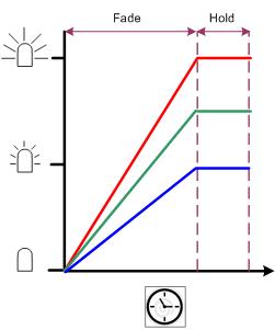 |
fig 2.
 |
Saving
the Internal Oscillator calibration instruction.
For
details on the internal oscillator calibration word, download the
Microchip datasheet for the 12F629 / 675 and read section 9.2 and in
particular sub-section 9.2.5.1
This
only applies to the 12F629 & 12F675. The 12F683 uses a
different method for calibration
See my tip to make
sure you will never lose the OSCCAL setting
If you have
erased the OSCCAL setting, use this circuit and code to recover it
FAQ:
-
Editing, adding changing the RGB sequence data.
All the sequence data is now held in the sequenceData.inc file so it
is really easy to add your own sequences. The application
works out how many sequences are present, where they start and
finish and takes care of page boundary crossing. All you have to do
is put the correctly formatted data into the file, save it then
reassemble.
Please take your time when editing the sequenceData.inc file since
errors are likely to cause the RGB Driver to do unexpected things or
crash.
If you see an 'Warning [220]' error during assembly like that shown
below, you've added more sequence data than the PIC has available
memory.
Clean: Deleting intermediary and output files.
Clean: Done.
Executing: "C:\Program Files\Microchip\MPASM Suite\MPAsmWin.exe" /q
/p12F675 "rgbsync_ctrl.asm" /l"rgbsync_ctrl.lst" /e"rgbsync-ctrl.err"
Warning[220] C:\CODE\RGBSA-INET.ASM 158 : Address exceeds maximum
range for this processor.
If you see an Error [112]
message during assembly check for missing comma separators in the
sequenceData.inc file
Clean: Deleting intermediary and output files.
Clean: Done.
Executing: "C:\Program Files\Microchip\MPASM Suite\MPAsmWin.exe" /q
/p12F675 "rgbsync_ctrl.asm" /l"rgbsync_ctrl.lst" /e"rgbsync_ctrl.err"
Error[112] C:\CODE\SEQUENCEDATA.INC 56 : Missing operator
-
Errors caused by
limitations of MPASM
While MPLAB IDE is a Windows application, the MPASM assembler has
its roots in the DOS era and this can cause a number of peculiar
errors when you come to 'quickbuild' the source code.
Error[173] .... Source file path exceeds 62 characters
Windows is happy with a long
file path but MPASM doesn't like anything over 62 characters so
MPLAB IDE will let you create, edit and save to a path like this but
MPASM won't assemble the file.
C:\DOCUMENTS AND SETTINGS\SOMEUSER\PICPROJECTS\ALONGDIRECTORYPATH\SSRGBCTL\RGBSYNC_CTRL.ASM
Error[151] ..... : Operand contains
unresolvable labels or is too complex
This strange error is caused by the '.' in
PIC.CODE
in the file path shown below:
C:\PIC.CODE\SSRGBCTL\RGBSYNC_INT.INC
Take the '.' out like this
"C:\PICCODE\SSRGBCTL\RGBSYNC_INT.INC"
and the code will assemble just
fine.
Contact us:
 |