| |
|
|
|
Mini projects |
|
|
|
|
|
- Electronic Die*
Built using a
PIC16F84, about 4 hours worth of code and a few bits on a breadboard. This
was the first time I've worked with PIC's so it was a learning exercise. I
started with the 'Hello World' microcontroller equivalent i.e.
Blinking LED, then tried the 'Knight Rider' sequencing LEDs, and then
hacked this together. The code is written and assembled using the Microchip
MPLAP
IDE V5.70. I only did this as an exercise to familiarise myself
with PIC assembler, but having got it working I decided I wanted it
smaller and as I had just acquired some 12F675s I took the original
16F84 code and developed it further to work with the 12F675.
For those of you who don't know, and to save
you the trouble of sending me an email to point out your
ignorance, dice is the plural of die
see here.
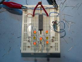
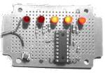
LED die using
PIC16F84 Die on bread board,
and
Programmer (the neat
PCB to left) with Die breadboard foreground and my circa 1985 Computer
PSU, modified to get supply for PIC programmer. The assembler code
was written to work, not as an example I'm afraid, so no apologies for the
quality. I haven't done any further work with this since I
decided the 8pin PIC12F675 was better suited for building a miniature
die. You should also note that if you do build a die using
the 16F84 code below it is flawed in that it throws with unequal
probability.
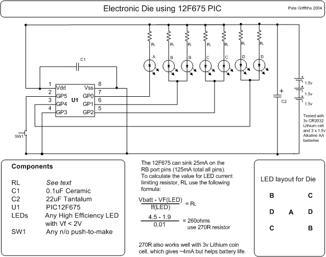
LED die using PIC12F675. Starting with the 16F84 code above I've modified and developed it
further to run on an 8 pin 12F675 device.
This device has an internal 4Mhz oscillator so it needs no external
support components and results in this minimum part die.
I got this PIC for £0.99p so I reckon you can build the whole
thing for about £2.50. You don't need a power switch since
the PIC 'sleeps' between throws and uses just a few micro Amps in
this state.
- PCB Artwork
Three months after I built these prototypes I finally got
round to producing a PCB for the die. The artwork is
available from the link below. Rather than using
discrete resistors the PCB layout uses a 9 pin 270R SIL resistor
pack (Actually only needs an 8 pin one, the PCB will accommodate
either). When you fit the button cell battery holder, check
to make sure it doesn't short out any of the component leads
behind it. You do need to use high efficiency LEDs with this
otherwise they won't be bright enough and if you increase the
current by reducing the value of the resistor pack it will impact
on battery life.
The artwork above is the second revision of the PCB. The
photo's below show the die built on the first PCB version I did.
This is pretty much identical to the second, I just manually
tweaked some of the auto routed tracks and removed the connector
for an external power connector.
Top image. Bottom
image
-
Operation
When the die first starts after power
is applied it initialise the device and then goes to sleep until the SW1 'roll'
button is pressed. While the button is pressed the display is
blank. On releasing the button the LEDs 'spin' for about 5 seconds.
The 'throw' is then display for 20 seconds at the end of which the
LEDs fade down and turn off over about 2 seconds. If the throw button
is pressed during this time, the die throws again, otherwise after 22
seconds the die goes back to sleep. I've built four of these
die, all running from CR2032 3V lithium cells. One of these
which I keep on my desk is still working on the original battery after
15 months.
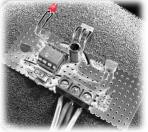
Here's an Ultra Small
Die that I've built using a 12F675. This would be ideal
for a surface mount design but I
haven't gone that far with it.
This is built on an tiny bit of strip board, with some careful assembly
and creative use of a baked bean can I've got down to the size of a 50
pence piece.
-
Front
View,
-
Rear View
before attaching battery holder
-
Completed with
battery holder attached (made from lid of Baked Bean can) attached.
-
Third
one with SM battery holder, PIC soldered directly into
circuit.
| March 2007
For some reason the 16F690 PIC
seems quite popular so here's yet another version of the die
using that PIC. While making the necessary
changes to the 12F675 code for it to run on a 16F690 I also
cleaned the original code up a bit and made it easier to
change LED and switch port pins so you don't have to dig
through the code to do it.
Source ASM and .HEX files
can be downloaded here die690inet.zip
Sorry, no schematic for
this. Use the one for the 12F675
here but make
connections to the 16F690 as shown below. Because we have
plenty of pins on this PIC, if you have a programmer with an
ICSP connector, you can hook it up directly using the pins
shown, if you don't ignore it.
__ __
[ICSP 5V ] Vdd -|1 20|- Vss [ICSP Ov ]
n/c -|2
19|- n/c [ICSP CLK ]
[ICSP Vpp] n/c -|3 18|- n/c [ICSP DAT ]
n/c -|4
17|- SW1
n/c -|5
16|- n/c
LEDA -|6 15|-
n/c
LEDB -|7 14|-
n/c
LEDC -|8 13|-
n/c
LEDD -|9 12|-
n/c
n/c -|10 11|-
n/c
-----
n/c -> no connection
[ ICSP aaa ] if you want to program the PIC using
ICSP
|
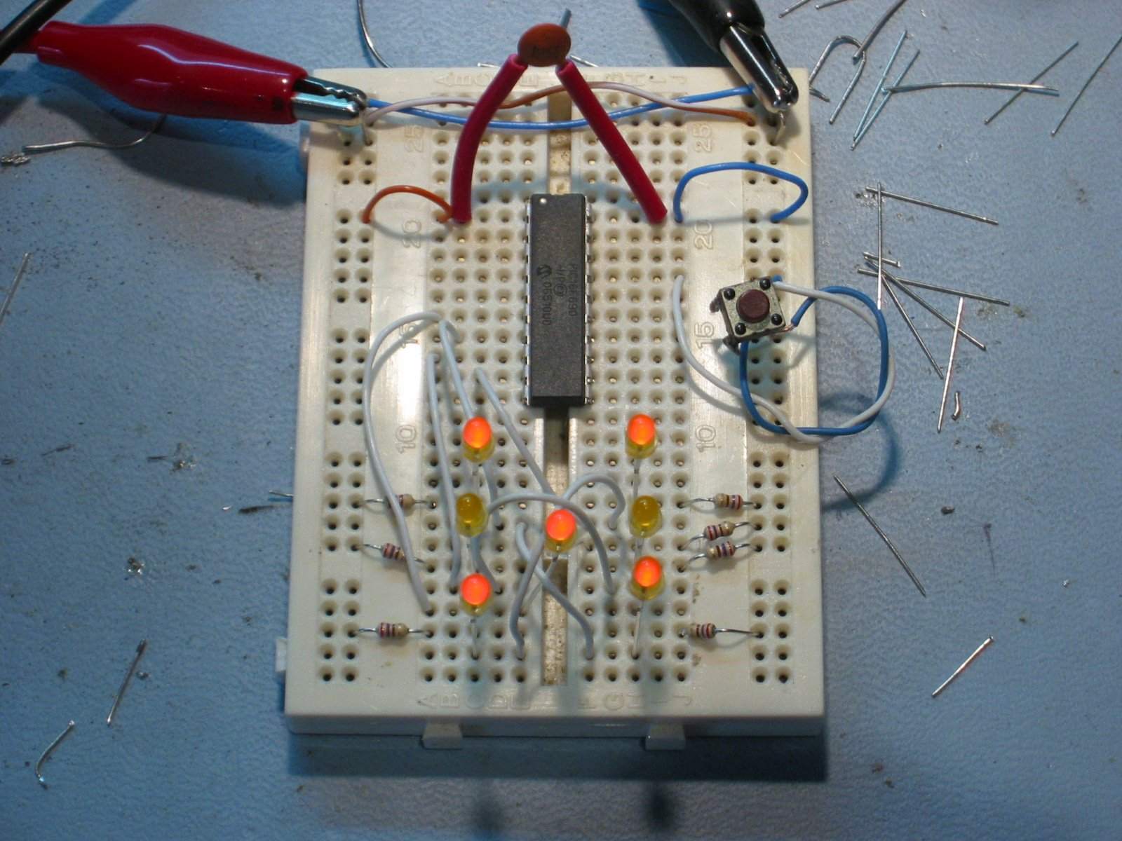
Running on my bread board.
The LEDs look a bit dim here as I was testing with a 3 volt
supply but the resistors were selected for 5 volts.LED
Arrangement for die display
B C
D A D
C B |
-
Electronic Dice,
I
designed and built this around 1985 using discrete 7400 series TTL
logic. I found it while digging out all the useful stuff
that has laid around since I last played with electronics in the early
1980's. I show it here just out of interest.
-
12F675
as Flip Flop Code to
make a 12F675 operate as a D-type or JK-type flip flop Since
I implemented a D type flip flop using the PIC Logic Elements I
thought I might go the other way and implement an entire D type
flip flop in a single PIC. This uses the edge triggered and
port change status interrupts and was an opportunity to have a play with
interrupts on the PIC. As
written this code will cause a PIC to function as a negative edge
triggered D type flip flop with active low Set and Reset inputs.
'D' type flip flop
Following the D type flip flop I've
hacked it round to make a JK flip flop. This implementation has one
extra 'feature' that a normal discrete logic device doesn't
have. After a reset, port GPIO5 (pin 2) is read and the logic level
used to select either a positive or negative clock edge.
GPIO5 = 1, negative edge (GPIO5 uses weak pull-up, so no
external resistor is needed)
GPIO5 = 0, positive edge
'JK' type flip flop
This circuit receives the signal from a
IR remote control, like those used to control your TV or DVD player and
allows the signal to be repeated in another location.
To get a 40Khz carrier requires an output to be toggled
on and off 40,000 times a second, which means the code needs to execute in
1,000,000/40,000 instruction cycles; this gives a very tight 25
instructions in which to do the job. Fortunately it's an easy job to do
so most of the instructions are just used to waste cycles. It's
not easy to get an accurate frequency with so little time and few
instructions cycles to play with but the IR receivers will work
several Khz either side of their design detection frequency so it's not
a problem.
This code can generate a 40Khz, 38.4Khz
or 37Khz carrier with a ~15% duty cycle. The frequencies are configurable in the source
code such that once programmed GPIO5 input on the PIC allows the
selection of two frequencies. By default the code is set to
produce 40Khz and 37Khz carriers which are modulated by the logic level
on GPIO2. This would generally be connected to a IR decoder IC.
One thing I did find with the Sony
equipment (I haven't tested it with anything else), 875nM IR LEDs don't
seem to work, but the 950nM one specified works well. (TSUS5400, Mfg
Vishay. Available from Farnell,
part number 178302)

Rapid Online - Rapid Electronics Ltd.
(See
big LED version here)
My nephews got a
Scalextric
slot car racing circuit from Santa for Christmas. This was a blast-from-the-past for my brother and me and we were soon showing the
kids how to race. However it quickly became apparent that
"3-2-1-Go" wasn't the best way to start a race so I put this
together to simulate the gantry lights used for starting F1 motor races.
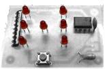
When the circuit is first powered on
LED's D2 and D4 light just to indicate the circuit is operating.
When the start button (SW2) is pressed
all the LED's turn off. They then illuminate sequentially at one second
intervals until all five LED's are on. After a random interval
between 0 and about 7 seconds the LED's extinguish, signaling the start
of the race.
Once the LED's have extinguished simply
press the start button again to initiate another race start
sequence. While waiting for the start button to be pressed the PIC
is put into a sleep state. This drops the current consumption to
around 10uA
Notes:
-
The circuit is really quite
simple. I tested it on a breadboard with standard 5mm red
LED's using 220R resistors from a 5Volt supply. The one on
the prototype board operates at 3Volts using two AA
cells. I dropped the value of the LED current limiting
resistors to 150R for this since the LED's I used weren't
hi-efficiency types. If you can use hi-efficiency LEDs you
could probably use 270R or 330R resistors and operate it
from a CR2032 3Volt Lithium coin cell.
-
With all five LEDs on,
the
prototype circuit was drawing about 25mA from a 3V supply. This
drops to a meagre 10uA with all LEDs off which should allow the
circuit to operate for many months, or even years depending on
use, from a couple of AA
cells without the need for a power switch.
-
The code enables weak-pull up on
the Port B pins but the unused Port A pins are all configured as
inputs and need pulling down to Vss.
-
The interval between each LED
turning on is
consistent and approximately 1 second. Timing is done
using the internal timer which in turn runs from the internal
clock. I'm happy that it's good enough for this application but
if millisecond accurate timing is needed (I can't think why)
you'll need to look elsewhere.
A new version of this circuit that can
be used with Scalextric Sport and similar slot car tracks has jump-start
detection. Full details are here
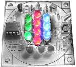
Now have their own pages.
Click here for the
RGB LED PWM Controller
Click here for the
Serial controlled RGB LED PWM Driver
Click here for the
High Power RGB LED PWM Driver
Click here for the
Addressable Serial Controlled RGB LED PWM
Driver
This code runs on a PIC
16F627A or 628A (and A.F.A.I.K 627/628 parts). It uses the serial
USART on the PIC to communicate with a PC. Through this a simple CLI
(Command Line Interface) is implemented that allows commands to be sent
to the PIC to control output lines and read and return the status of
inputs on the PIC
The serial interface is
configured to operate at 9600bps, 8bits, No Parity, 1 stop bit.
Port A is configured as
the output port, not forgetting that RA4 is an 'input only'. Port
B is used as the input port, again RB1 and RB2 are used by the PIC USART
so aren't available. In addition I have reserved RB0 for a Dallas 1-wire
interface. Although the code isn't implemented here, the RB0 port along
with RB1 and RB2 is masked from the input status command so bits RB2,1,0
always return 0.
To summarise;
Outputs are RA0-3, RA5-7
Inputs are RB3-7
The CLI commands and
functions are described below:
;
; Code displays the following message after a reset
; 'PIC Serial IO controller ready'
; A '#' is used as the command prompt.
; A '?' is sent to the terminal when any command is either not
; recognised, or contains invalid or insufficient arguments.
;
; Commands (All commands are lowercase except the Restart command)
;
; v - display firmware version
; i - display value on input port
; o - display value of outputReg variable (see below)
; nx - set output bit x
; fx - clear output bit x
; tx - toggle output bit x
; where x is in the range 1 to 8 or 0 to operate on all bits simultaneously
; sxxxxxxxx/ - set output to bit pattern specified by xxxxxxxx mask
; where x must be 0 or 1. MSB is leftmost.
; All 8 bits must be specified and must terminate with '/'
;
; c - Continuous monitor and display of the input port
; . - Stop continuous monitor of the input port and return to command prompt
;
; m[io] - Toggle port value display format [ i = input, o = output ]
; displays port value as hex 'HH' or binary 'bbbbbbbb' MSB leftmost
; At startup the format will be hex.
;
; p[io] - Toggles between displaying the port status only, or printing a text string
; followed by the port status.
; e.g. with text "Input status : A5", without "A5"
; At startup print mode will be port status only, no preceding
text.
;
; w[ed] - Enable or Disable the weak pull-up feature on Port B
; Weak Pull Up is disabled at startup.
;
; R - Do a software restart (note: Uppercase R)
;
;
; Note: All output commands work on the outputReg memory variable.
; This is copied to the output port register on completion of each command.
; The show output port command does not read the port register, it reads
; and displays the value in the outputReg memory variable.
Screen
dump of a sample terminal session
-
Source
Code (ZIP archive)
-
Hex (right-click Save As) for 16F627A (also
tested with 16F628A)
Notes:
-
There are no schematics for this
since it's designed as a building block. You will need to
interface pins RB1 and RB2 to a serial interface. RB1 is RXD input
and RB2 is TXD output. The code configures the PIC to use the
internal 4Mhz oscillator so no external crystal is needed.
-
You can use a MAX232 or one of the many variants, to interface to a
PC serial port. However, the schematic and PCB layout shown here for a
simple
discrete RS232 interface is cheap and and easy to construct and I've found
it works
well, or rather I've not found anything it hasn't worked with.
(I found the circuit design on the Net, I changed the transistors
for types I had in my parts box and in fact you can use pretty much
any general purpose NPN / PNP transistors here)
-
There are numerous applications and
languages that can be used to communicate with and issue commands to
the controller via a PC serial port. I've used a free
software terminal emulator called TeraTerm
while developing the code. The TeraTerm application also
features an easy-to-use macro command language that can be used to
automate the controller.
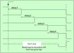
This code will
work with a 12F629, 12F675 or 12F683.
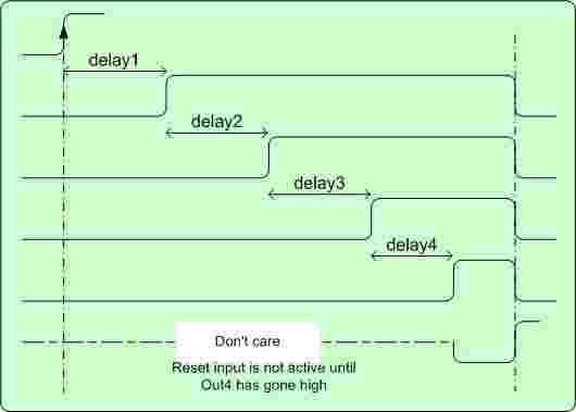
A rising edge on
the Trigger input starts a delay timer. At the end of the delay
period Output 1 goes high and a second delay timer is started.
At the end of the second delay Output 2 goes high. This is
repeated for Outputs 3 and 4. The result is four outputs that go
high in sequence with user defined delays between each one.
Once Output 4 has
gone high, a high level on the Reset input causes all four
outputs to clear and the program goes back to the initial state
waiting for a rising edge on the trigger input.
Each delay is
independent and configurable. The delay can be set either
to a period of 0 to 255mS in 1mS intervals, or a period of 0 to
25,500mS in 100mS intervals.
If the Reset input
is tied high, the code will automatically reset as soon as Out4
goes high.
|
 |
The four delay periods are
set by constants at lines 74-77 of the ASM file.
Each of the four delays
can be set to multiples of 1mS or 100mS. To do this you will need
to edit the .ASM file at the following lines. You can have a mix
of 1ms and 100mS delays depending on your requirement.
-
Delay1 edit line 137
-
Delay2 edit line 148
-
Delay3 edit line 159
-
Delay4 edit line 170
The download ASM file is
set for 1mS delays. To use 100mS delays, edit the call changing
_Delay to _LDelay
then reassemble the file.
call _Delay
; call 1mS delay function
; change _Delay above to _LDelay for delay with
100mS intervals
The code was produced
after I was contacted by someone who need a PIC to do this. They only
needed two outputs but to make it more useful I've added the two extra
outputs and the Reset input.
|